Toyota Tacoma (2015-2018) Service Manual: Power Outlet Socket(for Rear Side)
Components
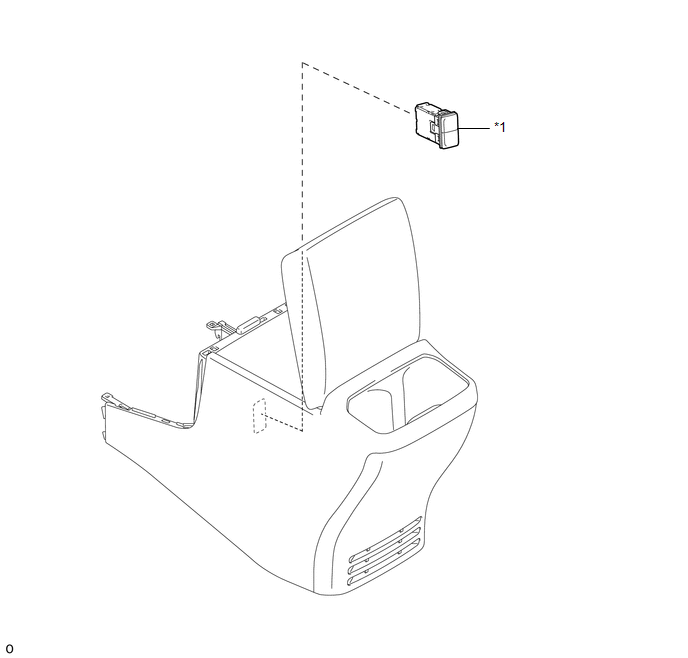
COMPONENTS
ILLUSTRATION
|
*1 |
USB CHARGER SOCKET |
- |
- |
Removal
REMOVAL
PROCEDURE
1. REMOVE REAR CONSOLE BOX ASSEMBLY
Click here .gif)
2. REMOVE USB CHARGER SOCKET
|
(a) Disengage the 4 claws to remove the USB charger socket. |
|
Installation
INSTALLATION
PROCEDURE
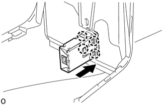
1. INSTALL USB CHARGER SOCKET
(a) Engage the 4 claws to install the USB charger socket.
2. INSTALL REAR CONSOLE BOX ASSEMBLY
Click here .gif)
 Power Outlet Socket(for Front Side)
Components
COMPONENTS
ILLUSTRATION
Removal
REMOVAL
PROCEDURE
1. REMOVE INSTRUMENT PANEL LOWER CENTER FINISH PANEL
(See page )
2. REMOVE NO. 1 POWER OUTLET SOCKET ASSEMBLY
(a ...
 Rear Power Outlet Socket
Components
COMPONENTS
ILLUSTRATION
ILLUSTRATION
Installation
INSTALLATION
PROCEDURE
1. INSTALL POWER OUTLET SOCKET ASSEMBLY
(a) Install the clamp.
(b) Connect the connector.
...
Other materials:
On-vehicle Inspection
ON-VEHICLE INSPECTION
PROCEDURE
1. INSPECT LOWER NO. 1 INSTRUMENT PANEL AIRBAG ASSEMBLY (for Vehicle not Involved
in Collision)
(a) Perform a diagnostic system check (See page
).
(b) With the lower No. 1 instrument panel airbag assembly ...
Parking Brake Switch Circuit
DESCRIPTION
This circuit is from the parking brake switch assembly to the radio and display
receiver assembly.
WIRING DIAGRAM
PROCEDURE
1.
CHECK VEHICLE SIGNAL
(a) Display the "Vehicle Signal Check Mode" screen (See page
).
...
Noise Occurs
PROCEDURE
1.
NOISE CONDITION
(a) Check from which direction the noise comes (front left or right, or rear
left or right).
OK:
The location of the noise source can be determined.
NG
GO TO STEP 3
OK
...
