Toyota Tacoma (2015-2018) Service Manual: Inspection
INSPECTION
PROCEDURE
1. INSPECT WATER INLET WITH THERMOSTAT SUB-ASSEMBLY
HINT:
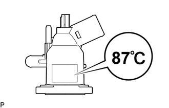
The valve opening temperature is inscribed on the water inlet with thermostat sub-assembly.
(a) Immerse the thermostat in the water, then heat the water gradually.
CAUTION:
- Do not your hands into the water that has been heated for the inspection.
- Touching the heated water could result in burns.
(b) Check the valve opening temperature of the water inlet with thermostat sub-assembly.
Standard valve opening temperature:
85 to 89°C (185 to 192°F)
NOTICE:
When checking the water inlet with thermostat sub-assembly in water, keep the terminals dry. After the check, wipe the water inlet with thermostat sub-assembly dry.
If the valve opening temperature is not as specified, replace the water inlet with thermostat sub-assembly.
|
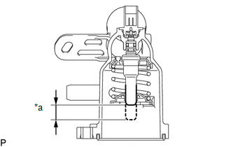
(c) Check the valve lift. Text in Illustration
Standard valve lift: 8.0 mm (0.315 in.) or more at 100°C (212°F) If the valve lift is not as specified, replace the water inlet with thermostat sub-assembly. |
|
(d) Check that the valve is fully closed when the water inlet with thermostat sub-assembly is at a low temperature (below 40°C (104°F)).
If the valve is not fully closed, replace the water inlet with thermostat sub-assembly.
(e) Measure the resistance according to the value(s) in the table below.
Standard Resistance:
|
Tester Connection |
Condition |
Specified Condition |
|---|---|---|
|
1 - 2 |
20°C (68°F) |
10.54 to 14.26 Ω |
If the result is not as specified, replace the water inlet with thermostat sub-assembly.
 Removal
REMOVAL
PROCEDURE
1. REMOVE NO. 2 ENGINE UNDER COVER SUB-ASSEMBLY (w/ Off Road Package)
2. REMOVE NO. 1 ENGINE UNDER COVER SUB-ASSEMBLY
3. DRAIN ENGINE COOLANT
4. REMOVE V-BANK COVER SUB-ASSEM ...
 Installation
INSTALLATION
PROCEDURE
1. INSTALL WATER INLET WITH THERMOSTAT SUB-ASSEMBLY
(a) Install a new gasket to the water inlet with thermostat sub-assembly.
(b) Install the water inlet with thermostat sub ...
Other materials:
Mirror Heater does not Operate with Rear Defogger Switch
DESCRIPTION
When the mirror heater switch on the air conditioning control assembly is pressed,
the operation signal is sent to the air conditioning amplifier assembly. When the
air conditioning amplifier assembly receives the signal, it turns on a relay in
the air conditioning amplifier assem ...
Terminals Of Ecu
TERMINALS OF ECU
1. NAVIGATION RECEIVER ASSEMBLY
Terminal No. (Symbols)
Wiring Color
Terminal Description
Condition
Specified Condition
N19-3 (ACC2) - N24-7 (GND1)*3
Y - W-B
Power source (ACC)
...
Operation Check
OPERATION CHECK
INPUT SIGNAL CHECK
*a
+RES
*b
-SET
*c
ON-OFF
*d
CANCEL
(a) Connect the Techstream to the DLC3.
(b) Check the cruise control main switch using the Data List functio ...
