Toyota Tacoma (2015-2018) Service Manual: Power Outlet Socket(for Front Side)
Components
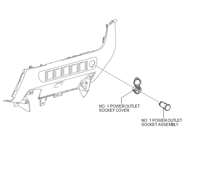
COMPONENTS
ILLUSTRATION
Removal
REMOVAL
PROCEDURE
1. REMOVE INSTRUMENT PANEL LOWER CENTER FINISH PANEL
(See page .gif) )
)
2. REMOVE NO. 1 POWER OUTLET SOCKET ASSEMBLY
|
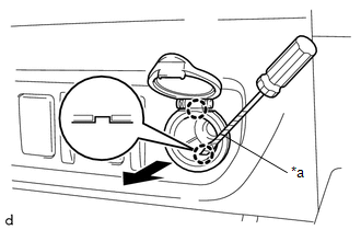
(a) Using a screwdriver with its tip wrapped in protective tape, disengage the 2 claws to remove the No. 1 power outlet socket assembly as shown in the illustration. Text in Illustration
|
|
3. REMOVE NO. 1 POWER OUTLET SOCKET COVER
|
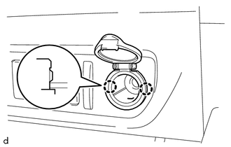
(a) Disengage the 2 claws to remove the No. 1 power outlet socket cover. |
|
Installation
INSTALLATION
PROCEDURE
1. INSTALL NO. 1 POWER OUTLET SOCKET COVER
(a) Engage the 2 claws to install the No. 1 power outlet socket cover.
2. INSTALL NO. 1 POWER OUTLET SOCKET ASSEMBLY
|
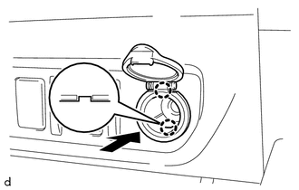
(a) Engage the 2 claws to install the No. 1 power outlet socket assembly as shown in the illustration. |
|
3. INSTALL INSTRUMENT PANEL LOWER CENTER FINISH PANEL
(See page .gif) )
)
 Inverter Relay
On-vehicle Inspection
ON-VEHICLE INSPECTION
PROCEDURE
1. INSPECT INVERTER RELAY
(a) Check the resistance.
(1) Measure the resistance according to the value(s) in the table below.
...
 Power Outlet Socket(for Rear Side)
Components
COMPONENTS
ILLUSTRATION
*1
USB CHARGER SOCKET
-
-
Removal
REMOVAL
PROCEDURE
1. REMOVE REAR CONSOLE BOX ASSEMBLY
Click here ...
Other materials:
Engine Immobiliser System Incorrect Assembly (B279C95)
DESCRIPTION
This code is stored when an ECM that is incompatible with the engine immobiliser
system is installed to the vehicle.
DTC Code
DTC Detection Condition
Trouble Area
DTC Output Confirmation Operation
B279C95
An ECM ...
Installation
INSTALLATION
PROCEDURE
1. INSTALL RADIATOR GRILLE
(a) Engage the 10 guides to install the radiator grille.
(b) Install the 2 clips.
(c) Install the 2 screws.
(d) Remove the protective tape.
(e) w/ Toyota Safety Sense P
(1) Engage the clamp.
(2) Connect the connector.
2. ADJUST MILLIMETER W ...
On-vehicle Inspection
ON-VEHICLE INSPECTION
PROCEDURE
1. INSPECT CAMSHAFT TIMING OIL CONTROL SOLENOID ASSEMBLY (for Intake Side)
(a) Connect the Techstream to the DLC3.
(b) Start the engine.
(c) Turn the Techstream on.
(d) Enter the following menus: Powertrain / Engine / Active Test / Control the
Intake VVT OCV D ...
