Toyota Tacoma (2015-2018) Service Manual: Parts Location
PARTS LOCATION
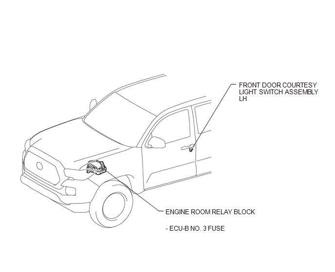
ILLUSTRATION
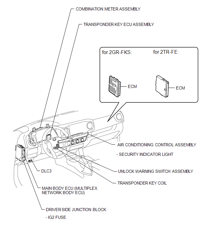
ILLUSTRATION

 Precaution
PRECAUTION
1. PRECAUTIONS WHEN USING TECHSTREAM
(a) When using the Techstream to troubleshoot the engine immobiliser system:
Connect the Techstream to the DLC3 while the ignition switch is off, and ...
Other materials:
Sound of Portable Player cannot be Heard from Speakers or Sound is Low
PROCEDURE
1.
CHECK PORTABLE PLAYER SETTINGS
(a) Check the portable player settings.
(1) Check that the volume is not set to "0".
(2) Check that the mute is off.
(b) Check that the sound of the portable player can be heard from the speakers.
OK:
Sound ...
Parts Location
PARTS LOCATION
ILLUSTRATION
*A
for Automatic Transmission
-
-
*1
FRONT SPEED SENSOR LH
*2
FRONT SPEED SENSOR RH
*3
FRONT AXLE WITH ABS ROTOR BEARING ASSEMBLY LH
- FRONT SP ...
Precaution
PRECAUTION
1. EXPRESSIONS OF IGNITION SWITCH
HINT:
The type of ignition switch used on this model differs according to the specifications
of the vehicle. The expressions listed in the table below are used in this section.
Expression
Ignition Switch
(Position)
...
