Toyota Tacoma (2015-2018) Service Manual: Clearance Sonar Main Switch Circuit
DESCRIPTION
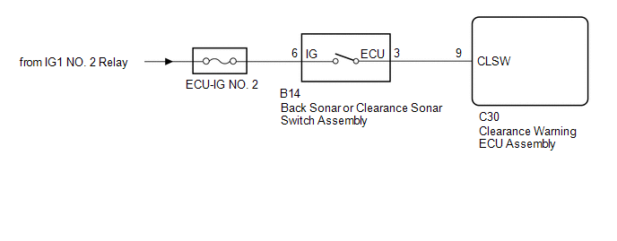
The back sonar or clearance sonar switch assembly is installed at the base of the driver side of the instrument panel.
When the back sonar or clearance sonar switch assembly is turned on, an on signal is sent to the clearance warning ECU assembly. The intuitive parking assist system operates according to this signal.
WIRING DIAGRAM
CAUTION / NOTICE / HINT
NOTICE:
Inspect the fuse for circuits related to this system before performing the following inspection procedure.
PROCEDURE
|
1. |
READ VALUE USING TECHSTREAM |
(a) Connect the Techstream to the DLC3.
(b) Turn the ignition switch to ON.
(c) Turn the Techstream on.
(d) Enter the following menus: Body Electrical / Intuitive P/A / Data List.
(e) According to the display on the Techstream, read the Data List.
Intuitive P/A|
Tester Display |
Measurement Item/Range |
Normal Condition |
Diagnostic Note |
|---|---|---|---|
|
Main Switch |
Back sonar or clearance sonar switch assembly/OFF or ON |
OFF: Back sonar or clearance sonar switch assembly off ON: Back sonar or clearance sonar switch assembly on |
- |
|
Intuitive P/A ECU Type |
Type of intuitive P/A ECU/Normal |
Normal: Normal clearance sonar type |
- |
|
Result |
Proceed to |
|---|---|
|
Both of the following conditions are met:
|
A |
|
"Normal" is not displayed. |
B |
|
Both of the following conditions are met:
|
C |
| A | .gif) |
PROCEED TO NEXT SUSPECTED AREA SHOWN IN PROBLEM SYMPTOMS TABLE |
| B | |
REPLACE CLEARANCE WARNING ECU ASSEMBLY |
|
.gif)
|
2. |
INSPECT BACK SONAR OR CLEARANCE SONAR SWITCH ASSEMBLY |
(a) Remove the back sonar or clearance sonar switch assembly (See page
.gif) ).
).
|
(b) Measure the resistance according to the value(s) in the table below. Standard Resistance:
|
|
| NG | |
REPLACE BACK SONAR OR CLEARANCE SONAR SWITCH ASSEMBLY |
|
|
3. |
CHECK HARNESS AND CONNECTOR (BACK SONAR OR CLEARANCE SONAR SWITCH ASSEMBLY POWER SOURCE) |
(a) Measure the voltage according to the value(s) in the table below.
Standard Voltage:
|
Tester Connection |
Condition |
Specified Condition |
|---|---|---|
|
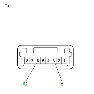
B14-6 (IG) - Body ground |
Ignition switch ON |
11 to 14 V |
|
B14-6 (IG) - Body ground |
Ignition switch off |
Below 1 V |
| NG | |
REPAIR OR REPLACE HARNESS OR CONNECTOR |
|
|
4. |
CHECK HARNESS AND CONNECTOR (BACK SONAR OR CLEARANCE SONAR SWITCH ASSEMBLY - CLEARANCE WARNING ECU ASSEMBLY) |
(a) Measure the resistance according to the value(s) in the table below.
Standard Resistance:
|
Tester Connection |
Condition |
Specified Condition |
|---|---|---|
|
C30-9 (CLSW) - B14-3 (ECU) |
Always |
Below 1 Ω |
|
C30-9 (CLSW) - Body ground |
Always |
10 kΩ or higher |
| OK | |
REPLACE CLEARANCE WARNING ECU ASSEMBLY |
| NG | |
REPAIR OR REPLACE HARNESS OR CONNECTOR |
 Rear Left Center Sensor Malfunction (C1AE7)
DESCRIPTION
The No. 1 ultrasonic sensor (rear center sensor LH) is installed on the rear
bumper. The ECU detects obstacles based on signals received from the No. 1 ultrasonic
sensor (rear center ...
 Clearance Warning Buzzer Circuit
DESCRIPTION
This circuit consists of the No. 1 clearance warning buzzer and clearance warning
ECU assembly. An ECU-excited type buzzer is used. The battery voltage supplied through
the buzzer is ...
Other materials:
Rear Power Outlet Socket
Components
COMPONENTS
ILLUSTRATION
ILLUSTRATION
Installation
INSTALLATION
PROCEDURE
1. INSTALL POWER OUTLET SOCKET ASSEMBLY
(a) Install the clamp.
(b) Connect the connector.
(c) Using a torx socket wrench T30, install the 4 screws and the power
outlet socket assemb ...
Black Screen
PROCEDURE
1.
CHECK DISPLAY SETTING
(a) Check that the display is not in "Screen Off" mode.
OK:
The display setting is not in "Screen Off" mode.
NG
CHANGE SCREEN TO SCREEN ON MODE
OK
...
Vehicle Speed Sensor (C1A45)
DESCRIPTION
The blind spot monitor sensor receives vehicle speed signals from the skid control
ECU (brake actuator assembly) via CAN communication.
DTC Code
DTC Detection Condition
Trouble Area
C1A45
A fail flag is transmitted from the ...
