Toyota Tacoma (2015-2018) Service Manual: On-vehicle Inspection
ON-VEHICLE INSPECTION
PROCEDURE
1. INSPECT DRIVE BELT
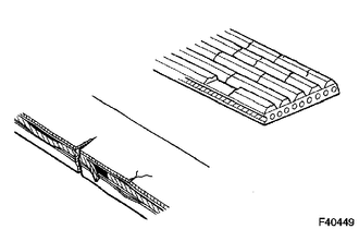
(a) Visually check the belt for defects, such as excessive wear and frayed cords.
If any defects are found, replace the drive belt.
HINT:
Replace the belt if there are any missing ribs.
2. BLEED POWER STEERING SYSTEM
(a) Check the fluid level.
(b) Jack up the front of the vehicle and support it with stands.
(c) Turn the steering wheel.
(1) With the engine stopped, turn the wheel slowly from lock to lock several times.
(d) Lower the vehicle.
(e) Start the engine.
(1) Run the engine at idle for a few minutes.
(f) Turn the steering wheel.
(1) With the engine idling, turn the wheel to the left or right full lock position and keep it there for 2 to 3 seconds. Then turn the wheel to the opposite full lock position and keep it there for 2 to 3 seconds (step A).
(2) Repeat step A several times.
(g) Stop the engine.
|
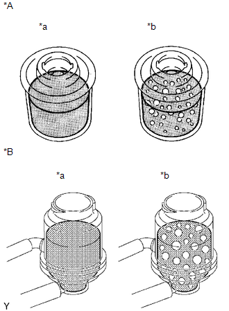
(h) Check for foaming or emulsification. Text in Illustration
Especially, if the system has to be bled twice because of foaming or emulsification, check for fluid leakage in the system. |
|
(i) Check the fluid level.
3. INSPECT FLUID LEVEL
(a) Keep the vehicle level.
|
(b) With the engine stopped, check the fluid level in the oil reservoir. Text in Illustration
Fluid: ATF "DEXRON" II or III HINT: Check that the fluid level is within the HOT level range in the reservoir tank. If the fluid is cold, check that it is within the COLD level range. If necessary, add fluid. |
|

(c) Start the engine and let it idle.
(d) Turn the steering wheel from lock to lock several times to raise fluid temperature.
Fluid temperature:
75 to 80°C (167 to 176°F)
|
(e) Check for foaming or emulsification. Text in Illustration
If any foaming or emulsification is identified, bleed the power steering system. |
|
|
(f) With the engine idling, measure the fluid level in the oil reservoir. Text in Illustration
|
|

(g) Stop the engine.
(h) Wait a few minutes and measure the fluid level in the oil reservoir again.
Maximum fluid level rise:
5 mm (0.197 in.)
If any problems are found, bleed the power steering system.
(i) Check the fluid level.
4. INSPECT STEERING FLUID PRESSURE
(a) for 2TR-FE:
(1) Disconnect the pressure feed tube from the vane pump (See page
.gif) ).
).
(b) for 2GR-FKS:
(1) Disconnect the pressure feed tube from the vane pump (See page
).
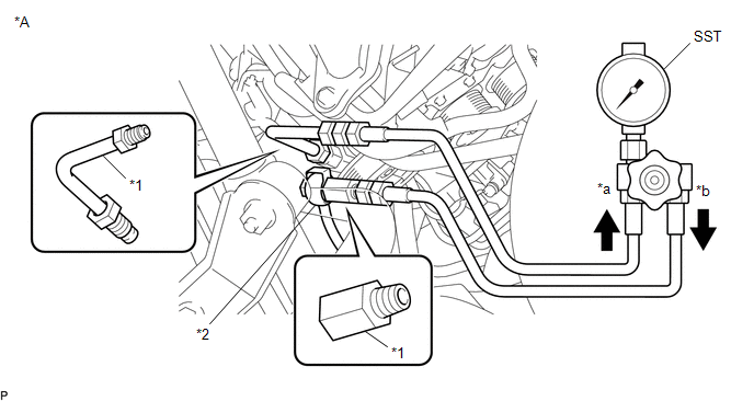
(c) for 2TR-FE:
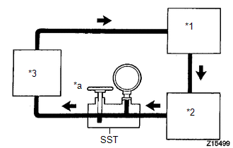
(1) Connect SST as shown in the illustration.
SST: 09640-10010
09641-01010
09641-01030
09641-01060
NOTICE:
Check that the valve of SST is in the open position.

|
*A |
for 2TR-FE |
- |
- |
|
*1 |
Attachment |
*2 |
Pressure Feed Tube |
|
*a |
In |
*b |
Out |
(d) for 2GR-FKS:
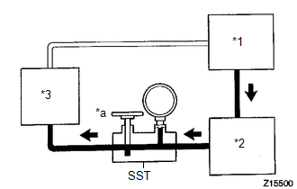
(1) Connect SST as shown in the illustration.
SST: 09640-10010
09641-01010
09641-01030
09641-01060
NOTICE:
Check that the valve of SST is in the open position.
|
*A |
for 2GR-FKS |
- |
- |
|
*1 |
Attachment |
*2 |
Pressure Feed Tube |
|
*a |
In |
*b |
Out |
(e) Bleed the power steering system.
(f) Start the engine and let it idle.
(g) Turn the steering wheel from lock to lock several times to raise the fluid temperature.
Fluid temperature:
75 to 80°C (167 to 176°F)
|
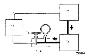
(h) With the engine idling, close the valve of SST and check the reading on SST. Text in Illustration
Fluid pressure: for 2TR-FE 8300 to 8800 kPa (84.7 to 89.7 kgf/cm2, 1204 to 1276 psi) for 2GR-FKS 8800 to 9300 kPa (89.8 to 94.8 kgf/cm2, 1276 to 1348 psi) NOTICE:
|
|
|
(i) With the engine idling, fully open the valve. Text in Illustration
|
|
(j) Measure the fluid pressure at the engine speeds of 1000 rpm and 3000 rpm.
Fluid pressure difference:
490 kPa (4.99 kgf/cm2, 71 psi) or less
NOTICE:
Do not turn the steering wheel.
|
(k) With the engine idling and valve fully open, turn the steering wheel to the full lock position. Text in Illustration
Fluid pressure: for 2TR-FE 8300 to 8800 kPa (84.7 to 89.7 kgf/cm2, 1204 to 1276 psi) for 2GR-FKS 8800 to 9300 kPa (89.8 to 94.8 kgf/cm2, 1276 to 1348 psi) NOTICE:
|
|
(l) Disconnect SST.
(m) for 2TR-FE:
(1) Connect the pressure feed tube to the vane pump (See page
).
(n) for 2GR-FKS:
(1) Connect the pressure feed tube to the vane pump (See page
).
(o) Bleed the power steering system.
5. INSPECT STEERING EFFORT

(a) Center the steering wheel assembly.
(b) Remove the horn button assembly (See page
).
(c) Start the engine and let it idle.
(d) Measure the steering effort in both directions.
Steering effort (Reference):
6.0 N*m (60 kgf*cm, 53 in.*lbf) or less
HINT:
Check the tire type, pressure and contact surfaces before making a diagnosis.
(e) Install the steering wheel assembly set nut.
Torque:
50 N·m {510 kgf·cm, 37 ft·lbf}
(f) Install the horn button assembly (See page
).

 Precaution
PRECAUTION
1. HANDLING PRECAUTIONS FOR STEERING SYSTEM
(a) Care must be taken when replacing parts. Incorrect replacement could affect
the performance of the steering system and result in driving ...
Other materials:
Data List / Active Test
DATA LIST / ACTIVE TEST
1. DATA LIST
HINT:
Using the Techstream to read the Data List allows the values or states of switches,
sensors, actuators and other items to be read without removing any parts. This non-intrusive
inspection can be very useful because intermittent conditions or signals ...
Installation
INSTALLATION
PROCEDURE
1. INSTALL CLUTCH DISC ASSEMBLY
(a) Insert SST into the clutch disc assembly, and then install SST and the clutch
disc assembly together to the flywheel sub-assembly.
Text in Illustration
Flywheel Sub-assembly Side
SST: 09301-00220
NOTICE ...
Rear Differential Lock Solenoid Circuit Low (P17C0)
DESCRIPTION
This DTC is output when a malfunction is detected due to a short to ground occurring
in the differential lock coil drive circuit of the rear differential.
DTC No.
Detection Item
DTC Detection Condition
Trouble Area
P17C0
...
