Toyota Tacoma (2015-2018) Service Manual: Parts Location
PARTS LOCATION
ILLUSTRATION
|
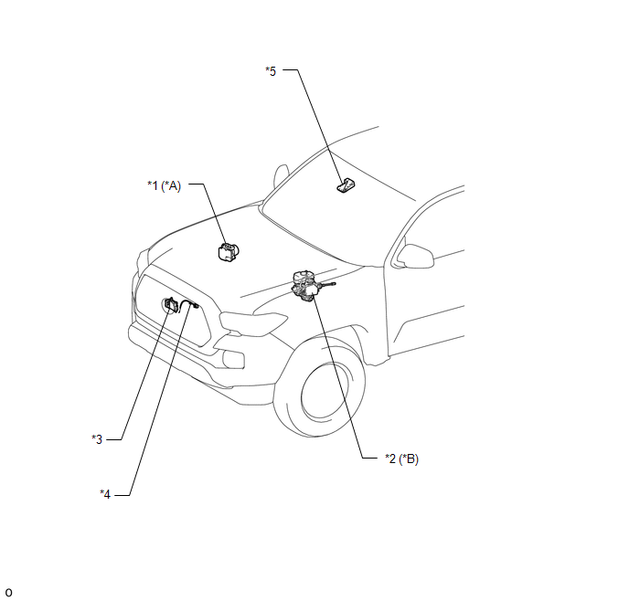
*A |
for Vacuum Brake Booster |
*B |
for Hydraulic Brake Booster |
|
*1 |
SKID CONTROL ECU (BRAKE ACTUATOR ASSEMBLY) |
*2 |
SKID CONTROL ECU (MASTER CYLINDER SOLENOID) |
|
*3 |
MILLIMETER WAVE RADAR SENSOR ASSEMBLY |
*4 |
MILLIMETER WAVE RADAR WIRE |
|
*5 |
FORWARD RECOGNITION CAMERA |
- |
- |
ILLUSTRATION
|
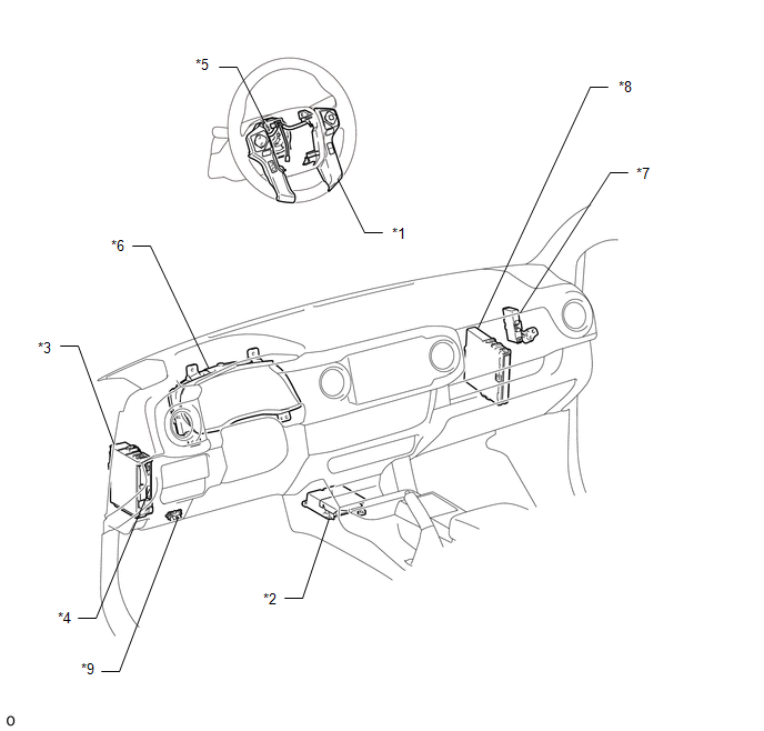
*1 |
STEERING PAD SWITCH ASSEMBLY - LANE DEPARTURE ALERT MAIN SWITCH - CUSTOMIZE SWITCH |
*2 |
YAW RATE AND ACCELERATION SENSOR (AIRBAG SENSOR ASSEMBLY) |
|
*3 |
DRIVER SIDE JUNCTION BLOCK - IG1 NO. 2 FUSE - ECU-IG NO. 2 FUSE |
*4 |
MAIN BODY ECU (MULTIPLEX NETWORK BODY ECU) |
|
*5 |
SPIRAL CABLE WITH SENSOR SUB-ASSEMBLY |
*6 |
COMBINATION METER ASSEMBLY |
|
*7 |
NETWORK GATEWAY ECU |
*8 |
ECM |
|
*9 |
DLC3 |
- |
- |
 Precaution
PRECAUTION
PRECAUTION FOR DISCONNECTING CABLE FROM NEGATIVE BATTERY TERMINAL
NOTICE:
When disconnecting the cable from the negative (-) battery terminal, initialize
the following systems after th ...
 System Description
SYSTEM DESCRIPTION
LANE DEPARTURE ALERT SYSTEM DESCRIPTION
(a) The lane departure alert system is a system which uses the forward recognition
camera to recognize and determine the lane and the pos ...
Other materials:
Diagnosis System
DIAGNOSIS SYSTEM
1. DESCRIPTION
(a) To check DTCs, connect the Techstream to the Data Link Connector 3 (DLC3)
of the vehicle. The Techstream displays DTCs and freeze frame data. The DTCs and
freeze frame data can be cleared with the Techstream (See page
).
2. NORMAL MODE AND CHECK MODE
(a) ...
Ptc Heater Relay
Components
COMPONENTS
ILLUSTRATION
Inspection
INSPECTION
PROCEDURE
1. INSPECT PTC HEATER RELAY
(a) Check the resistance.
(1) Measure the resistance according to the value(s) in the table below.
Standard Resistance:
Tester Connection
C ...
Output Shaft
Components
COMPONENTS
ILLUSTRATION
Disassembly
DISASSEMBLY
PROCEDURE
1. REMOVE FRONT OUTPUT SHAFT BEARING
(a) Temporarily install the manual transmission output shaft rear set
nut to the output shaft.
Text in Illustration
*1
Manual ...
