Toyota Tacoma (2015-2018) Service Manual: Parts Location
PARTS LOCATION
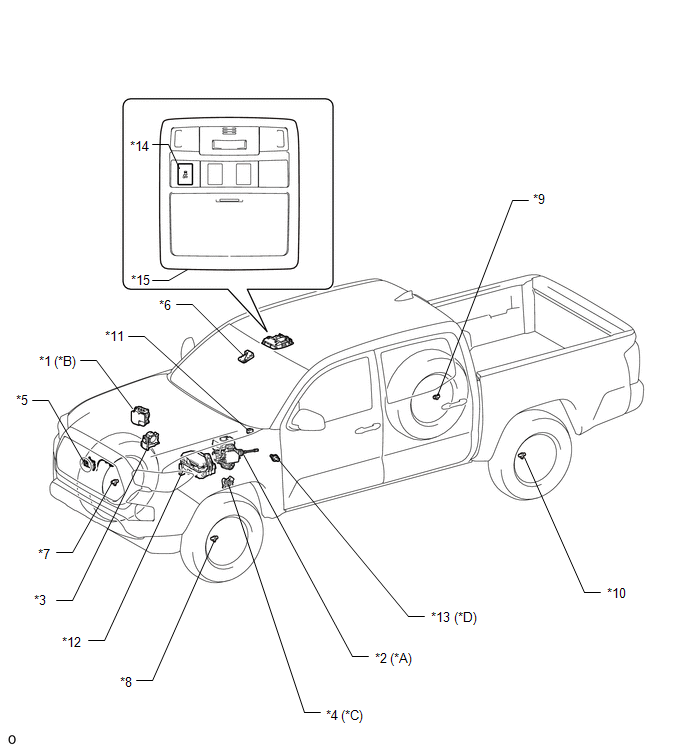
ILLUSTRATION
|
*A |
for Hydraulic Brake Booster |
*B |
for Vacuum Brake Booster |
|
*C |
for Automatic Transmission |
*D |
for Manual Transmission |
|
*1 |
SKID CONTROL ECU (BRAKE ACTUATOR ASSEMBLY) |
*2 |
SKID CONTROL ECU (MASTER CYLINDER SOLENOID) |
|
*3 |
THROTTLE BODY WITH MOTOR ASSEMBLY |
*4 |
PARK/NEUTRAL POSITION SWITCH |
|
*5 |
MILLIMETER WAVE RADAR SENSOR ASSEMBLY |
*6 |
FORWARD RECOGNITION CAMERA |
|
*7 |
FRONT SPEED SENSOR RH |
*8 |
FRONT SPEED SENSOR LH |
|
*9 |
REAR SPEED SENSOR RH |
*10 |
REAR SPEED SENSOR LH |
|
*11 |
SKID CONTROL BUZZER |
*12 |
ENGINE ROOM RELAY BLOCK - IG2 FUSE - EFI NO. 1 FUSE - ETCS FUSE - STOP FUSE - STOP RELAY |
|
*13 |
NEUTRAL POSITION SWITCH |
*14 |
VSC OFF SWITCH |
|
*15 |
ROOF CONSOLE BOX ASSEMBLY |
- |
- |
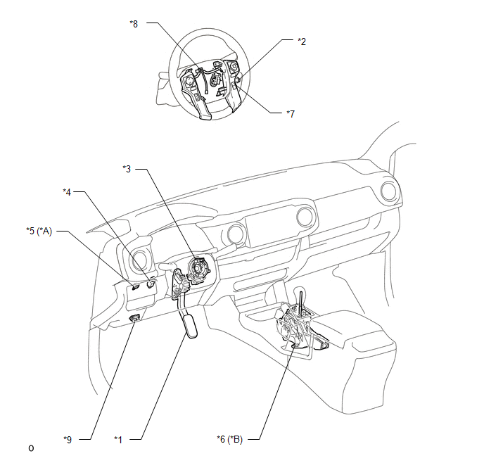
ILLUSTRATION
|
*A |
for Manual Transmission |
*B |
for Automatic Transmission |
|
*1 |
ACCELERATOR PEDAL SENSOR ASSEMBLY |
*2 |
CRUISE CONTROL MAIN SWITCH |
|
*3 |
STEERING ANGLE SENSOR (SPIRAL CABLE WITH SENSOR SUB-ASSEMBLY) |
*4 |
STOP LIGHT SWITCH ASSEMBLY |
|
*5 |
CLUTCH SWITCH ASSEMBLY |
*6 |
TRANSMISSION CONTROL SWITCH (TRANSMISSION FLOOR SHIFT ASSEMBLY ) |
|
*7 |
DISTANCE CONTROL SWITCH (STEERING PAD SWITCH ASSEMBLY) |
*8 |
CRUISE CONTROL SWITCH WIRE |
|
*9 |
DLC3 |
- |
- |
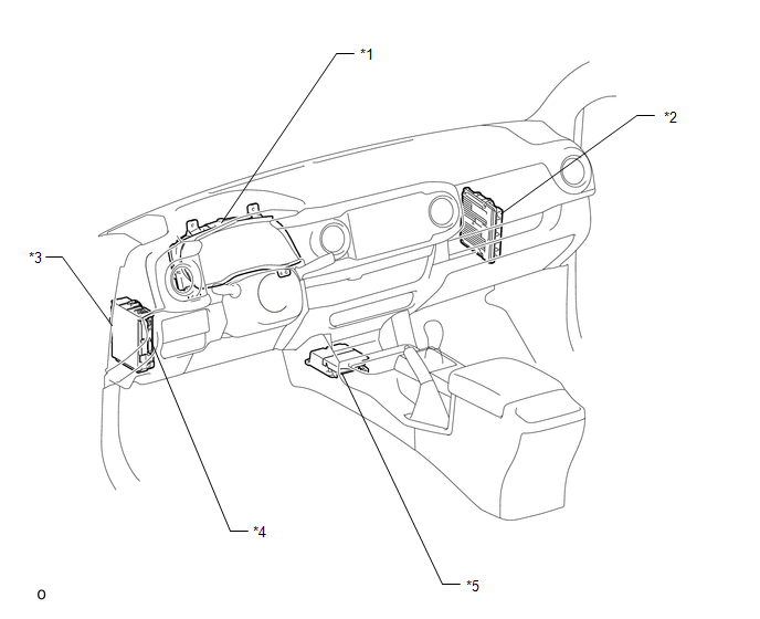
ILLUSTRATION
|
*1 |
COMBINATION METER ASSEMBLY |
*2 |
ECM |
|
*3 |
DRIVER SIDE JUNCTION BLOCK - IG1 NO. 2 FUSE - ECU-IG NO. 2 FUSE - IG1 NO. 1 FUSE - BKUP LP NO. 3 FUSE |
*4 |
MAIN BODY ECU (MULTIPLEX NETWORK BODY ECU) |
|
*5 |
YAW RATE AND ACCELERATION SENSOR (AIRBAG SENSOR ASSEMBLY) |
- |
- |
 Definition Of Terms
DEFINITION OF TERMS
Term
Definition
Monitor Description
Description of what the ECM monitors and how it detects malfunctions
(monitoring purpose ...
 System Diagram
SYSTEM DIAGRAM
Communication Table
Sender
Receiver
Signal
Line
ECM
Millimeter Wave Radar Sensor Assembly
...
Other materials:
Camper information
This information has been prepared in accordance with regulation issued by
the National Highway Traffic Safety Administration of the U.S. Department of Transportation.
It provides the purchasers and/or prospective purchasers of Toyota vehicles with
information on truck-camper loading. Your Toy ...
Installation
INSTALLATION
PROCEDURE
1. INSTALL GENERATOR ASSEMBLY
(a) Install the generator bracket to the generator assembly with the bolt.
Torque:
20 N·m {204 kgf·cm, 15 ft·lbf}
(b) Install the generator assembly with the 2 bolts.
Torque:
43 N·m {438 kgf·cm, 32 ft·lbf}
(c) Connect the generato ...
Reassembly
REASSEMBLY
PROCEDURE
1. INSTALL FRONT AXLE HUB OIL SEAL
(a) Using a brass bar and a hammer, install a new front axle hub oil seal.
NOTICE:
Do not damage the oil seal.
2. INSTALL FRONT AXLE WITH ABS ROTOR BEARING ASSEMBLY
(a) Using SST and a press, install a new bearing onto the front axle ...
