Toyota Tacoma (2015-2018) Service Manual: Open in Outer Mirror Indicator(Master) (C1AB4)
DESCRIPTION
This DTC is stored when the blind spot monitor sensor LH detects an open in the blind spot monitor indicator LH.
|
DTC Code |
DTC Detection Condition |
Trouble Area |
|---|---|---|
|
C1AB4 |
With the blind spot monitor main switch assembly (warning canceling switch assembly) on, the current flowing to the indicator is below a specified value when indicator operation voltage is sent to the indicator. |
|
WIRING DIAGRAM
CAUTION / NOTICE / HINT
NOTICE:
When checking for DTCs, make sure that the blind spot monitor main switch assembly (warning canceling switch assembly) is on.
PROCEDURE
|
1. |
CHECK DTC |
(a) Clear the DTCs (See page .gif) ).
).
(b) Recheck for DTCs and check if the same DTC is output again (See page
).
OK:
No DTCs are output.
| OK | .gif) |
USE SIMULATION METHOD TO CHECK |
|
.gif)
|
2. |
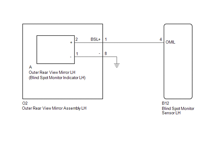
CHECK HARNESS AND CONNECTOR (OUTER REAR VIEW MIRROR ASSEMBLY LH - BLIND SPOT MONITOR SENSOR LH AND BODY GROUND) |
(a) Disconnect the B12 blind spot monitor sensor LH connector.
(b) Disconnect the O2 outer rear view mirror assembly LH connector.
(c) Measure the resistance according to the value(s) in the table below.
Standard Resistance:
|
Tester Connection |
Condition |
Specified Condition |
|---|---|---|
|
B12-4 (OMIL) - O2-1 (BSL+) |
Always |
Below 1 Ω |
|
O2-8 - Body ground |
Always |
Below 1 Ω |
| NG | |
REPAIR OR REPLACE HARNESS OR CONNECTOR |
|
|
3. |
INSPECT OUTER REAR VIEW MIRROR ASSEMBLY LH |
(a) Remove the outer rear view mirror assembly LH (See page
).
(b) Remove the outer rear view mirror LH (See page
).
(c) Measure the resistance according to the value(s) in the table below.
Standard Resistance:
|
Tester Connection |
Condition |
Specified Condition |
|---|---|---|
|
O2-1 (BSL+) - A-2 (+) |
Always |
Below 1 Ω |
|
O2-8 - A-1 (-) |
Always |
Below 1 Ω |
| NG | |
REPLACE OUTER REAR VIEW MIRROR ASSEMBLY LH |
|
|
4. |
CHECK OUTER REAR VIEW MIRROR LH |
(a) Replace the outer rear view mirror LH with a new or normally functioning
one (See page ).
(b) Clear the DTCs (See page ).
(c) Recheck for DTCs and check if the same DTC is output again (See page
).
OK:
No DTCs are output.
| OK | |
END (OUTER REAR VIEW MIRROR LH WAS DEFECTIVE) |
| NG | |
REPLACE BLIND SPOT MONITOR SENSOR LH |
 Blind Spot Monitor Master Module (C1AB6)
DESCRIPTION
This DTC is stored when the blind spot monitor sensor LH detects an internal
malfunction.
DTC Code
DTC Detection Condition
Trouble Area
...
 Short to GND in Outer Mirror Indicator(Master) (C1AB2)
DESCRIPTION
This DTC is stored when the blind spot monitor sensor LH detects a ground short
in the blind spot monitor indicator LH.
DTC Code
DTC Detection Condition
...
Other materials:
Pattern Select Switch
Components
COMPONENTS
ILLUSTRATION
Removal
REMOVAL
PROCEDURE
1. REMOVE INSTRUMENT PANEL LOWER CENTER FINISH PANEL
(See page )
2. REMOVE PATTERN SELECT SWITCH ASSEMBLY
(a) Detach the 2 claws to remove the pattern select switch assembly from
the instrument panel lower c ...
Disassembly
DISASSEMBLY
PROCEDURE
1. REMOVE BRAKE ACTUATOR BRACKET NO. 1
(a) Using a hexagon wrench (5 mm), remove the screw and brake actuator bracket
No. 1.
(b) Using a screwdriver, remove the fluid level warning switch connector.
2. REMOVE BRAKE M ...
Installation
INSTALLATION
CAUTION / NOTICE / HINT
HINT:
Perform "Inspection After Repairs" after replacing the engine assembly, cylinder
head sub-assembly, camshaft, No. 2 camshaft, No. 3 camshaft sub-assembly, No. 4
camshaft sub-assembly, camshaft timing gear assembly, camshaft timing exhaust g ...
