Toyota Tacoma (2015-2018) Service Manual: Short to GND in Outer Mirror Indicator(Master) (C1AB2)
DESCRIPTION
This DTC is stored when the blind spot monitor sensor LH detects a ground short in the blind spot monitor indicator LH.
|
DTC Code |
DTC Detection Condition |
Trouble Area |
|---|---|---|
|
C1AB2 |
With the blind spot monitor main switch assembly (warning canceling switch assembly) on, the voltage output from the blind spot monitor sensor to the indicator is low for a certain amount of time. |
|
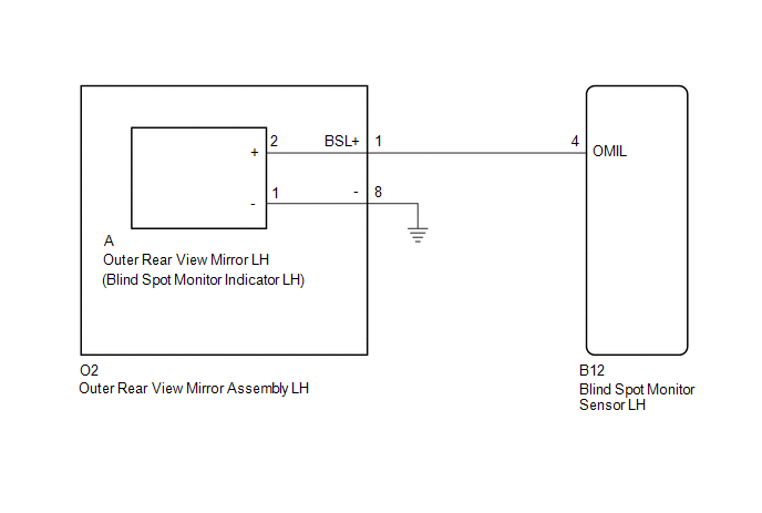
WIRING DIAGRAM
CAUTION / NOTICE / HINT
NOTICE:
When checking for DTCs, make sure that the blind spot monitor main switch assembly (warning canceling switch assembly) is on.
PROCEDURE
|
1. |
CHECK DTC |
(a) Clear the DTCs (See page .gif) ).
).
(b) Recheck for DTCs and check if the same DTC is output again (See page
).
OK:
No DTCs are output.
| OK | .gif) |
USE SIMULATION METHOD TO CHECK |
|
.gif)
|
2. |
CHECK HARNESS AND CONNECTOR (OUTER REAR VIEW MIRROR ASSEMBLY LH - BLIND SPOT MONITOR SENSOR LH) |
(a) Disconnect the O2 outer rear view mirror assembly LH connector.
(b) Disconnect the B12 blind spot monitor sensor LH connector.
(c) Measure the resistance according to the value(s) in the table below.
Standard Resistance:
|
Tester Connection |
Condition |
Specified Condition |
|---|---|---|
|
O2-1 (BSL+) - Body ground |
Always |
10 kΩ or higher |
| NG | |
REPAIR OR REPLACE HARNESS OR CONNECTOR |
|
|
3. |
CHECK HARNESS AND CONNECTOR (BLIND SPOT MONITOR SENSOR LH - OUTER REAR VIEW MIRROR LH) |
(a) Reconnect the O2 outer rear view mirror assembly LH connector.
|
(b) Disconnect the blind spot monitor sensor LH connector. |
|
(c) Disconnect the A outer rear view mirror LH connector.
(d) Measure the resistance according to the value(s) in the table below.
Standard Resistance:
|
Tester Connection |
Condition |
Specified Condition |
|---|---|---|
|
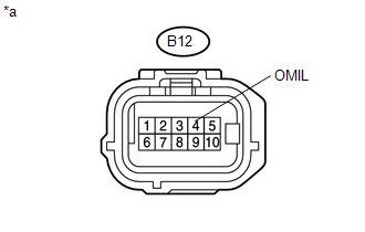
B12-4 (OMIL) - Body ground |
Always |
10 kΩ or higher |
|
*a |
Front view of wire harness connector (to Blind Spot Monitor Sensor LH) |
| NG | |
REPLACE OUTER REAR VIEW MIRROR ASSEMBLY LH |
|
|
4. |
CHECK OUTER REAR VIEW MIRROR LH |
(a) Replace the outer rear view mirror LH with a new or normally functioning
one (See page ).
(b) Clear the DTCs (See page ).
(c) Check for DTCs and check if the same DTC is output again (See page
).
OK:
No DTCs are output.
| OK | |
END (OUTER REAR VIEW MIRROR LH WAS DEFECTIVE) |
| NG | |
REPLACE BLIND SPOT MONITOR SENSOR LH |
 Open in Outer Mirror Indicator(Master) (C1AB4)
DESCRIPTION
This DTC is stored when the blind spot monitor sensor LH detects an open in the
blind spot monitor indicator LH.
DTC Code
DTC Detection Condition
Troub ...
 Short to GND in Outer Mirror Indicator(Slave) (C1AB3)
DESCRIPTION
This DTC is stored when the blind spot monitor sensor RH detects a ground short
in the blind spot monitor indicator RH.
DTC Code
DTC Detection Condition
...
Other materials:
General maintenance
Listed below are the general maintenance items that should be performed at
the intervals specified in the “Scheduled Maintenance Guide” or “Owner’s Manual
Supplement”. It is recommended that any problem you notice should be brought to
the attention of your Toyota dealer or qualified ...
Satellite Radio Broadcast cannot be Received
CAUTION / NOTICE / HINT
NOTICE:
Some satellite radio broadcasts require payment. A contract must be
made between a satellite radio company and the user. If the contract expires,
it will not be possible to listen to the broadcast.
After replacing the stereo component tuner assem ...
Passenger Side Buckle Switch Circuit Malfunction (B1771)
DESCRIPTION
The passenger side buckle switch circuit consists of the occupant detection ECU
and the front seat inner belt assembly RH.
DTC B1771 is recorded when a malfunction is detected in the passenger side buckle
switch circuit.
Troubleshoot DTC B1771 first when DTCs B1771 and B1795 are o ...
