Toyota Tacoma (2015-2018) Service Manual: Main Switch Power Source Circuit
DESCRIPTION
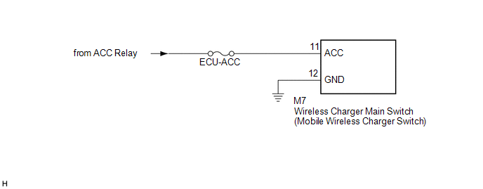
This circuit supplies power to the wireless charger main switch (mobile wireless charger switch) and illuminates the switch indicator light when the wireless charger main switch (mobile wireless charger switch) is turned on.
WIRING DIAGRAM
CAUTION / NOTICE / HINT
NOTICE:
Inspect the fuses for circuits related to this system before performing the following inspection procedure.
PROCEDURE
|
1. |
CHECK HARNESS AND CONNECTOR (WIRELESS CHARGER MAIN SWITCH (MOBILE WIRELESS CHARGER SWITCH) POWER SOURCE) |
(a) Disconnect the M7 wireless charger main switch (mobile wireless charger switch) connector.
(b) Measure the resistance according to the value(s) in the table below.
Standard Resistance:
|
Tester Connection |
Condition |
Specified Condition |
|---|---|---|
|
M7-12 (GND) - Body ground |
Always |
Below 1 Ω |
|
M7-11 (ACC) - Body ground |
Always |
10 kΩ or higher |
(c) Measure the voltage according to the value(s) in the table below.
Standard Voltage:
|
Tester Connection |
Switch Condition |
Specified Condition |
|---|---|---|
|
M7-11 (ACC) - M7-12 (GND) |
Ignition switch ACC |
11 to 14 V |
| OK | .gif) |
PROCEED TO NEXT SUSPECTED AREA SHOWN IN PROBLEM SYMPTOMS TABLE |
| NG | |
REPAIR OR REPLACE HARNESS OR CONNECTOR |
 Problem Symptoms Table
PROBLEM SYMPTOMS TABLE
HINT:
Use the table below to help determine the cause of problem symptoms.
If multiple suspected areas are listed, the potential causes of the symptoms
are lis ...
 Terminals Of Ecu
TERMINALS OF ECU
1. MOBILE WIRELESS CHARGER CRADLE ASSEMBLY
Tester Connection
Wiring Color
Terminal Description
Condition
Specified Condition ...
Other materials:
Terminals Of Ecu
TERMINALS OF ECU
1. CHECK AIR CONDITIONING AMPLIFIER ASSEMBLY (for Automatic Air Conditioning)
(See page )
2. CHECK AIR CONDITIONING AMPLIFIER ASSEMBLY (for Manual Air Conditioning)
(See page )
3. CHECK AIR CONDITIONING CONTROL ASSEMBLY (for Automatic Air Conditioning)
(See page )
4. CHECK ...
Components
COMPONENTS
ILLUSTRATION
ILLUSTRATION
ILLUSTRATION
*1
CAMSHAFT
*2
CAMSHAFT BEARING CAP
*3
CAMSHAFT HOUSING SUB-ASSEMBLY RH
*4
CAMSHAFT TIMING GEAR BOLT (for Intake Side of Bank 1)
...
Speed Sensor
Components
COMPONENTS
ILLUSTRATION
Removal
REMOVAL
PROCEDURE
1. REMOVE TRANSMISSION REVOLUTION SENSOR (NT)
(a) Disconnect the transmission revolution sensor (NT) connector.
(b) Remove the bolt and transmission revolution sensor (NT). ...
