Toyota Tacoma (2015-2018) Service Manual: Speed Sensor
Components
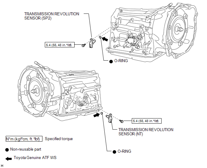
COMPONENTS
ILLUSTRATION
Removal
REMOVAL
PROCEDURE
1. REMOVE TRANSMISSION REVOLUTION SENSOR (NT)
|
(a) Disconnect the transmission revolution sensor (NT) connector. |
|
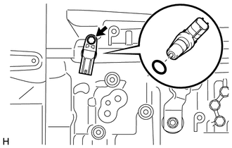
(b) Remove the bolt and transmission revolution sensor (NT).
(c) Remove the O-ring from the transmission revolution sensor (NT).
2. REMOVE TRANSMISSION REVOLUTION SENSOR (SP2)
|
(a) Disconnect the transmission revolution sensor (SP2) connector. |
|
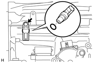
(b) Remove the bolt and transmission revolution sensor (SP2).
(c) Remove the O-ring from the transmission revolution sensor (SP2).
Inspection
INSPECTION
PROCEDURE
1. INSPECT TRANSMISSION REVOLUTION SENSOR (NT)
(a) Connect the battery to the transmission revolution sensor (NT) as shown in the illustration.
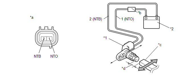 Text in Illustration
|
*1 |
Transmission Revolution Sensor (NT) |
*2 |
Battery |
|
*a |
Component without harness connected (Transmission Revolution Sensor (NT)) |
*b |
Ammeter |
|
*c |
Magnet |
*d |
5 mm (0.197 in.) or less |
(b) Wave a magnetic object left and right in front of the transmission revolution sensor (NT) tip (5 mm (0.197 in.) or less) to change the high/low signals while measuring the current.
NOTICE:
Make sure to wave the magnetic object during the inspection. The current will not change without waving the magnetic object as indicated by the arrow in the illustration.
(c) Measure the current according to the value(s) in the table below.
Standard Current:
|
Tester Connection |
Condition |
Specified Condition |
|---|---|---|
|
1 (NTO) - 2 (NTB) |
Low signal |
4 to 8 mA |
|
High signal |
12 to 16 mA |
If the result is not as specified, replace the transmission revolution sensor (NT).
2. INSPECT TRANSMISSION REVOLUTION SENSOR (SP2)
(a) Connect the battery to the transmission revolution sensor (SP2) as shown in the illustration.
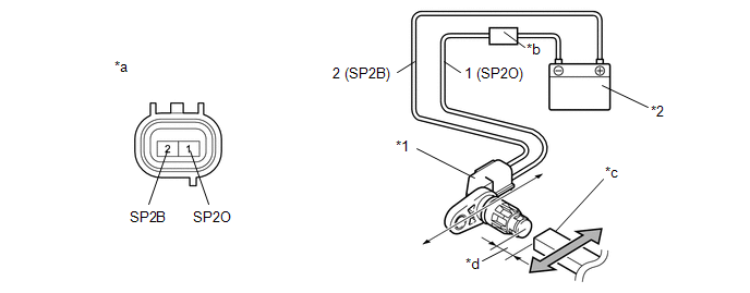 Text in Illustration
|
*1 |
Transmission Revolution Sensor (SP2) |
*2 |
Battery |
|
*a |
Component without harness connected (Transmission Revolution Sensor (SP2)) |
*b |
Ammeter |
|
*c |
Magnet |
*d |
5 mm (0.197 in.) or less |
(b) Wave a magnetic object left and right in front of the transmission revolution sensor (SP2) tip (5 mm (0.197 in.) or less) to change the high/low signals while measuring the current.
NOTICE:
Make sure to wave the magnetic object during the inspection. The current will not change without waving the magnetic object as indicated by the arrow in the illustration.
(c) Measure the current according to the value(s) in the table below.
Standard Current:
|
Tester Connection |
Condition |
Specified Condition |
|---|---|---|
|
1 (SP2O) - 2 (SP2B) |
Low signal |
4 to 8 mA |
|
High signal |
12 to 16 mA |
If the result is not as specified, replace the transmission revolution sensor (SP2).
Installation
INSTALLATION
PROCEDURE
1. INSTALL TRANSMISSION REVOLUTION SENSOR (SP2)
(a) Coat a new O-ring with ATF and install it to the transmission revolution sensor (SP2).
(b) Install the transmission revolution sensor (SP2) with the bolt.
Torque:
5.4 N·m {55 kgf·cm, 48 in·lbf}
(c) Connect the transmission revolution sensor (SP2) connector.
2. INSTALL TRANSMISSION REVOLUTION SENSOR (NT)
(a) Coat a new O-ring with ATF and install it to the transmission revolution sensor (NT).
(b) Install the transmission revolution sensor (NT) with the bolt.
Torque:
5.4 N·m {55 kgf·cm, 48 in·lbf}
(c) Connect the transmission revolution sensor (NT) connector.
 Reassembly
REASSEMBLY
PROCEDURE
1. INSTALL INDICATOR LIGHT WIRE SUB-ASSEMBLY
(a) Connect the connector to install the indicator light wire sub-assembly
to the shift position indicator.
...
 Torque Converter And Drive Plate
Inspection
INSPECTION
PROCEDURE
1. INSPECT TORQUE CONVERTER ASSEMBLY
(a) Inspect the one-way clutch.
(1) Press on the spline of the stator with a finger and rotate the spline. Check
that the ...
Other materials:
Diagnostic Trouble Code Chart
DIAGNOSTIC TROUBLE CODE CHART
Smart Key System
DTC Code
Detection Item
See page
B27A1
Open in Driver Side Electrical Antenna Circuit
B27A5
Open in Front Floor Electrical Key Oscillator Circuit
...
Mute Signal Circuit between Radio Receiver and Stereo Component Amplifier
DESCRIPTION
This circuit sends a signal to the stereo component amplifier assembly to mute
noise. Because of that, the noise produced by changing the sound source ceases.
If there is an open in the circuit, noise can be heard from the speakers when
changing the sound source.
If there is a sho ...
Stereo Component Amplifier Malfunction (B15A3)
DESCRIPTION
This DTC is stored when a malfunction occurs in the stereo component amplifier
assembly.
DTC No.
DTC Detection Condition
Trouble Area
B15A3
When one of the conditions below is met:
Internal power supply malfun ...
