Toyota Tacoma (2015-2018) Service Manual: Interior Illumination Light
Components
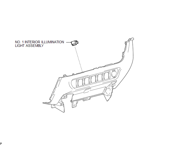
COMPONENTS
ILLUSTRATION
Removal
REMOVAL
PROCEDURE
1. REMOVE INSTRUMENT PANEL LOWER CENTER FINISH PANEL
(See page .gif) )
)
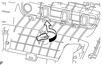
2. REMOVE NO. 1 INTERIOR ILLUMINATION LIGHT ASSEMBLY
|
(a) Turn the No. 1 interior illumination light assembly in the direction indicated by the arrow in the illustration to remove it. |
|
Installation
INSTALLATION
PROCEDURE
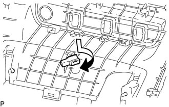
1. INSTALL NO. 1 INTERIOR ILLUMINATION LIGHT ASSEMBLY
|
(a) Turn the No. 1 interior illumination light assembly in the direction indicated by the arrow shown in the illustration to install it. |
|
2. INSTALL INSTRUMENT PANEL LOWER CENTER FINISH PANEL
(See page .gif) )
)
 Installation
INSTALLATION
PROCEDURE
1. INSTALL CENTER STOP LIGHT ASSEMBLY (for Bulb Type Stop Light)
(a) Install the 3 center stop light bulbs to the 3 center stop light sockets.
(b) Turn the 3 cent ...
 License Plate Light Assembly
Components
COMPONENTS
ILLUSTRATION
Removal
REMOVAL
CAUTION / NOTICE / HINT
HINT:
Use the same procedure for both the LH and RH sides.
The procedure described below is for the ...
Other materials:
Inspection
INSPECTION
PROCEDURE
1. INSPECT CYLINDER BLOCK FOR WARPAGE
(a) Using a precision straightedge and feeler gauge, measure the warpage
of the contact surface of the cylinder head gasket.
Standard warpage:
0 to 0.05 mm (0 to 0.00197 in.)
Maximum warpage:
0.07 mm (0.00276 ...
Disassembly
DISASSEMBLY
PROCEDURE
1. REMOVE GENERATOR PULLEY
(a) Mount the generator assembly in the vise between aluminum plates.
NOTICE:
Do not overtighten the vise.
(b) Install SST 1-A to the generator pulley shaft.
Text in Illustration
*a
Hold
Turn
...
Freeze Frame Data
FREEZE FRAME DATA
1. FREEZE FRAME DATA
(a) Whenever a DTC is detected, the blind spot monitor sensor stores the current
vehicle (sensor) state as Freeze Frame Data.
2. CHECK FREEZE FRAME DATA
(a) Connect the Techstream to the DLC3.
(b) Turn the ignition switch to ON.
(c) Turn the blind spot ...
