Toyota Tacoma (2015-2018) Service Manual: Removal
REMOVAL
PROCEDURE
1. REMOVE FRONT PILLAR GARNISH LH
(See page .gif) )
)
2. REMOVE ASSIST GRIP SUB-ASSEMBLY
(See page )
3. REMOVE FRONT PILLAR GARNISH RH
(See page )
4. REMOVE NO. 1 INSTRUMENT PANEL SPEAKER PANEL SUB-ASSEMBLY
(See page )
5. REMOVE NO. 2 INSTRUMENT PANEL SPEAKER PANEL SUB-ASSEMBLY
(See page )
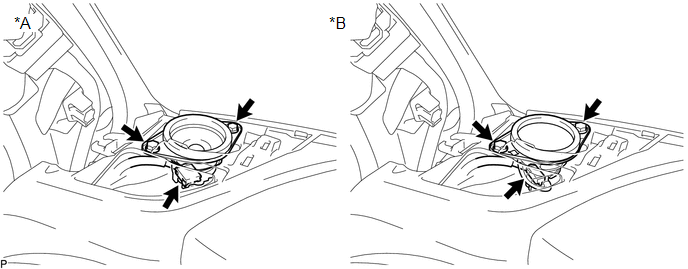
6. REMOVE FRONT NO. 2 SPEAKER ASSEMBLY LH
(a) Remove the 2 bolts.
 Text in Illustration
|
*A |
w/o Amplifier Box Speaker Assembly |
*B |
w/ Amplifier Box Speaker Assembly |
(b) Disconnect the connector to remove the front No. 2 speaker assembly LH.
NOTICE:
Do not touch the cone part of the front No. 2 speaker assembly LH.
7. REMOVE FRONT NO. 2 SPEAKER ASSEMBLY RH
(a) Remove the 2 bolts.
 Text in Illustration
|
*A |
w/o Amplifier Box Speaker Assembly |
*B |
w/ Amplifier Box Speaker Assembly |
(b) Disconnect the connector to remove the front No. 2 speaker assembly RH.
NOTICE:
Do not touch the cone part of the front No. 2 speaker assembly RH.
 Components
COMPONENTS
ILLUSTRATION
ILLUSTRATION
...
 Inspection
INSPECTION
PROCEDURE
1. INSPECT FRONT NO. 2 SPEAKER ASSEMBLY
(a) When there is a malfunction such as noise from a speaker or no sound at all,
replace the speaker with a new one and check that the ...
Other materials:
Operation Check
OPERATION CHECK
1. CHECK WINDOW LOCK SWITCH
HINT:
Before performing the window lock switch operation check, make sure that the
window lock switch is off (the switch is not pushed in).
(a) Check that the front passenger and rear windows cannot be operated from each
power window regulator swit ...
LVDS Signal Malfunction (from Extension Module) (B1532)
DESCRIPTION
The stereo component tuner assembly and the radio and display receiver assembly
are connected by an LVDS communication line.
This DTC is stored when an LVDS communication error occurs between the stereo
component tuner assembly and the radio and display receiver assembly.
...
Components
COMPONENTS
ILLUSTRATION
*A
w/ Fuel Tank Cover
*B
for Hydraulic Brake Booster
*1
FUEL TANK ASSEMBLY
*2
FUEL TANK INLET PIPE SUB-ASSEMBLY
*3
FUEL TANK VENT HOSE SUB-ASSEMBLY
...
