Toyota Tacoma (2015-2018) Service Manual: Removal
REMOVAL
PROCEDURE
1. REMOVE FRONT FENDER MUDGUARD (w/ Mudguard)
Click here .gif)
2. REMOVE FRONT FENDER WHEEL OPENING MOULDING (w/ Over Fender)
Click here
3. REMOVE FRONT NO. 1 WHEEL OPENING EXTENSION PAD (w/ Front Spoiler)
|
(a) Remove 9 screws and front No. 1 wheel opening extension pad. |
|
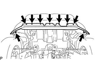
4. REMOVE RADIATOR GRILLE
Click here
5. REMOVE FRONT BUMPER ASSEMBLY
(a) w/o Over Fender:
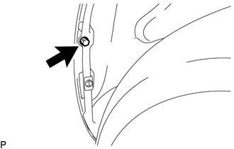
|
(1) Remove the screw. HINT: Use the same procedure for the RH side and LH side. |
|
|
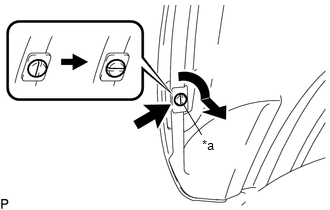
(b) Using a screwdriver, turn the pin 90 degrees and remove the pin hold clip. HINT: Use the same procedure for the RH side and LH side. |
|
|
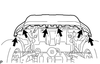
(c) Remove the 4 screws and 2 bolts. |
|
|
(d) Disconnect the connector. |
|
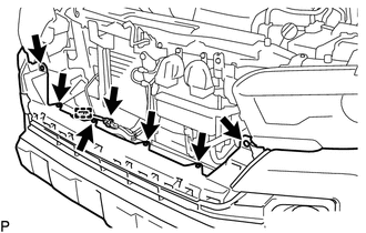
(e) Disengage the clamp.
(f) Remove the 6 clips.
|
(g) Put protective tape around the front bumper assembly. |
|
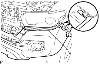
(h) Disengage the guide and 3 claws.
HINT:
Use the same procedure for the RH side and LH side.
(i) w/ Fog Light:
(1) Disconnect the 2 connectors.
(j) Remove the front bumper assembly.
 Reassembly
REASSEMBLY
PROCEDURE
1. INSTALL FRONT BUMPER COVER INSERT LH
(a) Engage the clip to install the front bumper cover insert LH.
(b) Install the b ...
 Installation
INSTALLATION
PROCEDURE
1. INSTALL FRONT BUMPER ASSEMBLY
(a) w/ Fog Light:
(1) Connect the 2 connectors.
(b) Engage the 3 claws and guide to install the front bumper assembly.
(c) Remove the prot ...
Other materials:
Door Unlock Detection Switch Circuit
DESCRIPTION
The main body ECU (multiplex network body ECU) detects the condition of each
door unlock detection switch.
WIRING DIAGRAM
CAUTION / NOTICE / HINT
NOTICE:
If the main body ECU (multiplex network body ECU) is replaced, refer to Registration
(See page ).*1
*1: w/ Smart K ...
Lost Communication with Alternator Missing Message (P161A87)
DESCRIPTION
The ECM communicates with the generator assembly via LIN communication. If a
LIN communication error is detected, the ECM stores this DTC.
DTC No.
DTC Detection Condition
Trouble Area
P161A87
Generator assembly or ECM commu ...
Differential Oil
Adjustment
ADJUSTMENT
PROCEDURE
1. INSPECT DIFFERENTIAL OIL
(a) Stop the vehicle on a level place.
(b) Remove the differential filler plug and gasket.
(c) Check that the oil level is within 5 mm (0 to 0.20 in.) of the bottom of
the filler plug opening.
NOTICE:
Excessively large ...
