Toyota Tacoma (2015-2018) Service Manual: Disassembly
DISASSEMBLY
PROCEDURE
1. REMOVE HOOD BULGE ASSEMBLY (w/ Hood Bulge)
|
(a) Remove the 4 nuts. |
|
(b) Disengage the clip from back side of the hood panel to remove the hood bulge assembly together with the air intake guide.
2. REMOVE NO. 2 HOOD BULGE PROTECTOR (w/ Hood Bulge)
|
(a) Remove the No. 2 hood bulge protector. |
|
3. REMOVE HOOD AIR INTAKE GUIDE (w/ Hood Bulge)
|
(a) Remove the 4 screws. |
|
(b) Disengage the 5 guides to remove the hood air intake guide.
4. REMOVE NO. 1 HOOD BULGE PROTECTOR (w/ Hood Bulge)
|
(a) Remove the No. 1 hood bulge protector. |
|
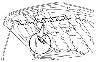
5. REMOVE HOOD TO RADIATOR SUPPORT SEAL
|
(a) Using a clip remover, remove the 7 clips and hood to radiator support seal. |
|
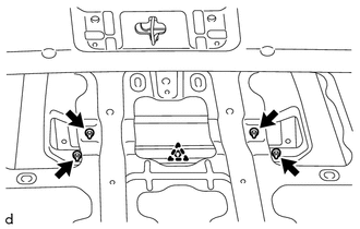
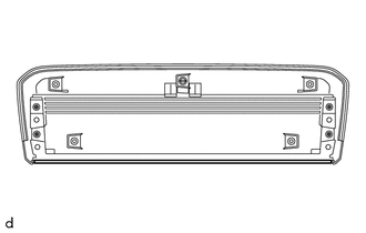
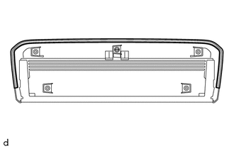
6. REMOVE WASHER NOZZLE SUB-ASSEMBLY
.gif)
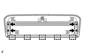
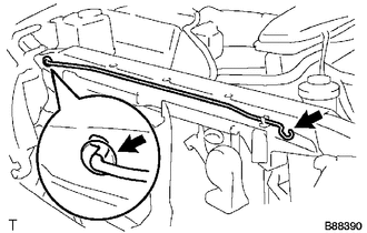
7. DISCONNECT WASHER HOSE ASSEMBLY
|
(a) Disengage the 4 clamps to disconnect the washer hose assembly. |
|
|
(b) Disengage the 4 claws to remove the 4 clamps. |
|
8. REMOVE RADIATOR GRILLE
9. REMOVE HOOD LOCK ASSEMBLY
10. REMOVE HOOD SUPPORT
|
(a) Remove the hood support. |
|
(b) Remove the grommet.
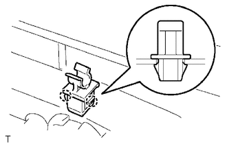
11. REMOVE HOOD STAY HOLDER
|
(a) Using a clip remover, disengage the 2 claws to remove the hood stay holder. |
|
12. REMOVE HOOD LOCK CONTROL LEVER SUB-ASSEMBLY
|
(a) Disengage the claw and 3 guides to remove the hood lock control lever sub-assembly. |
|
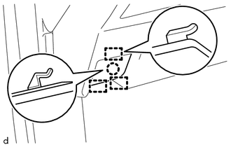
|
(b) Disconnect the hood lock control cable assembly to remove the hood lock control lever sub-assembly. |
|
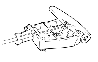
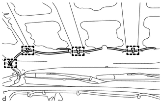
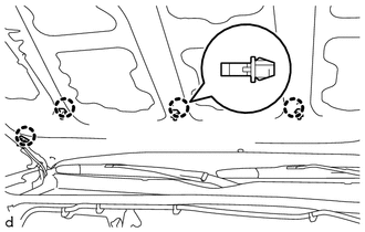
13. REMOVE HOOD LOCK CONTROL CABLE ASSEMBLY
|
(a) Tie a string to the end of the hood lock control cable assembly. HINT: Using a length of string long enough to pass through the motor compartment. |
|

(b) Disengage the 5 clamps and hood cable grommet as shown in the illustration.
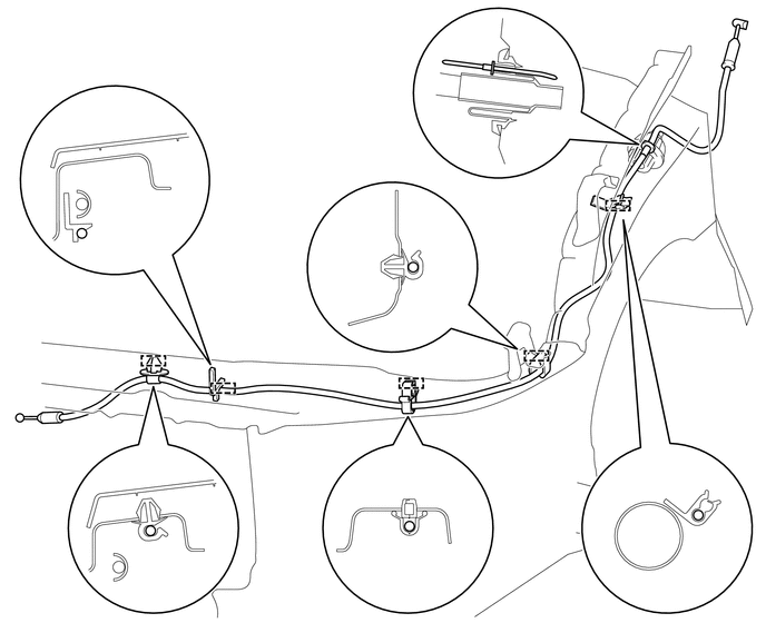
(c) Pull the hood lock control cable assembly from the engine compartment to remove it.
(d) Remove the string from the hood lock control cable assembly.
 Components
COMPONENTS
ILLUSTRATION
ILLUSTRATION
ILLUSTRATION
...
 Reassembly
REASSEMBLY
CAUTION / NOTICE / HINT
NOTICE:
When installing the hood bulge protector, heat the hood bulge surface
using the infrared light.
Do not heat the hood bulge excessively.
...
Other materials:
Installation
INSTALLATION
CAUTION / NOTICE / HINT
HINT:
Use the same procedures for both the LH and RH sides.
The procedure described below is for the LH side.
PROCEDURE
1. INSTALL OUTER REAR VIEW MIRROR ASSEMBLY
(a) Engage the claw to install the outer rear view mirror assembly.
(b) Ins ...
Intake Air Control Valve Actuator(for Acis)
Components
COMPONENTS
ILLUSTRATION
Inspection
INSPECTION
PROCEDURE
1. INSPECT INTAKE AIR CONTROL VALVE ACTUATOR
(a) Check the operate.
(1) Apply battery voltage to the connector, and check the operation of
the intake air control valve actuator gear.
Text in Illustrati ...
Removal
REMOVAL
PROCEDURE
1. REMOVE FUEL DELIVERY PIPE ASSEMBLY LH (FUEL PRESSURE SENSOR)
(See page )
NOTICE:
Do not remove the fuel pressure sensor from the fuel delivery pipe sub-assembly
LH.
If a fuel pressure sensor is removed, replace the fuel delivery pipe
sub-assembly LH (fu ...
