Toyota Tacoma (2015-2018) Service Manual: Components
COMPONENTS
ILLUSTRATION
ILLUSTRATION
ILLUSTRATION
 Adjustment
ADJUSTMENT
CAUTION / NOTICE / HINT
HINT:
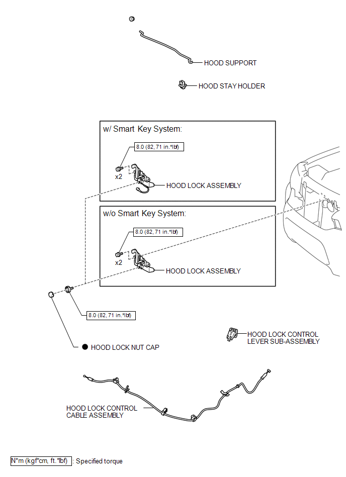
Centering bolts are used to mount the hood hinge and hood lock assembly.
The hood and hood lock assembly cannot be adjusted with the centering ...
 Disassembly
DISASSEMBLY
PROCEDURE
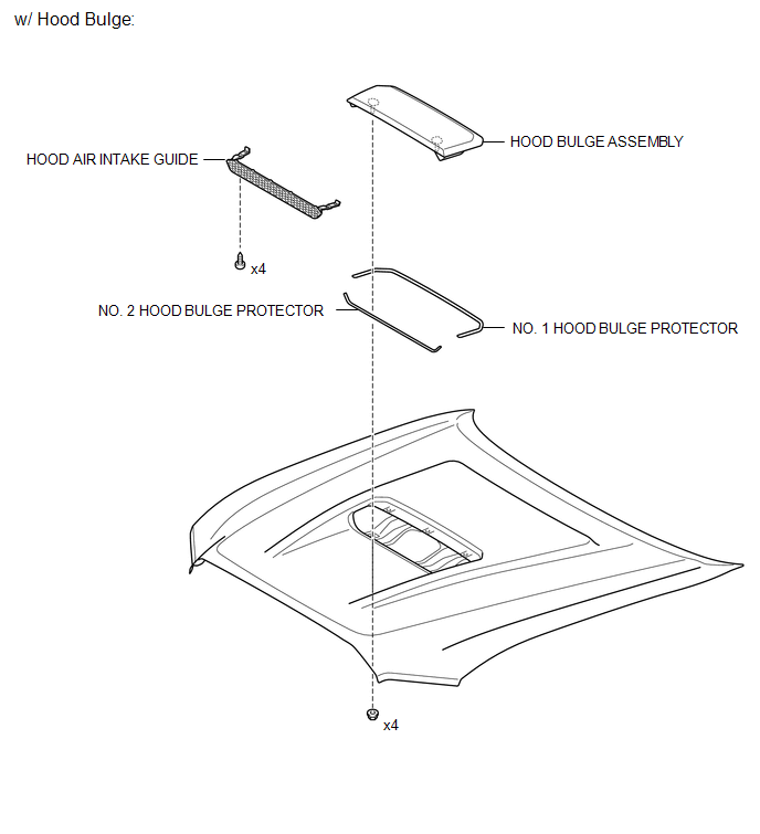
1. REMOVE HOOD BULGE ASSEMBLY (w/ Hood Bulge)
(a) Remove the 4 nuts.
(b) Disengage the clip from back side of the hood pa ...
Other materials:
Tire Pressure Monitor Receiver Communication Stop (B1247)
DESCRIPTION
The main body ECU (multiplex network body ECU) and tire pressure warning ECU
and receiver are connected using 2 direct lines that they use to communicate with
each other.
DTC No.
Detection Item
DTC Detection Condition
Trouble Area
...
Installation
INSTALLATION
PROCEDURE
1. REMOVE MONOLITHIC CONVERTER PROTECTOR
(a) Install the upper monolithic converter protector and lower monolithic converter
protector with the 2 bolts and 2 nuts.
Torque:
11 N·m {107 kgf·cm, 8 ft·lbf}
(b) Install the clamp with the bolt as shown in the ...
Transmitter ID not Received in Main Mode (C2126/26)
DESCRIPTION
After all transmitter IDs are registered, DTC C2126/26 is stored in the tire
pressure warning ECU and receiver and the tire pressure warning light blinks for
1 minute and then illuminates.
When the tire pressure warning ECU and receiver successfully receives radio waves
from all ...
