Toyota Tacoma (2015-2018) Service Manual: Disassembly
DISASSEMBLY
PROCEDURE
1. INSPECT FRONT DRIVE SHAFT
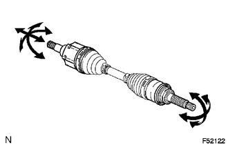
(a) Check whether there is no remarkable play in the outboard joint.
(b) Check whether the inboard joint slides smoothly in the thrust direction.
(c) Check whether there is no remarkable play in the radial direction of the inboard joint.
(d) Check the boots for damage.
NOTICE:
Move the drive shaft while keeping it level.
2. REMOVE FRONT AXLE INBOARD JOINT BOOT CLAMP
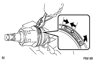
(a) Using pliers, disengage the hooks together and remove the large clamp.
(b) Using a side cutter, cut the small boot clamp.
3. SEPARATE INBOARD JOINT BOOT
(a) Slide the inboard joint boot toward the outboard joint.
4. REMOVE FRONT DRIVE INBOARD JOINT ASSEMBLY
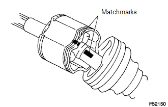
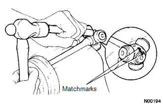
(a) Place matchmarks on the inboard joint and outboard joint shaft.
NOTICE:
Do not punch the marks.
(b) Remove the inboard joint from the outboard joint shaft.
|
(c) Using a snap ring expander, remove the snap ring. |
|
|
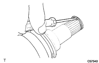
(d) Place matchmarks on the outboard joint shaft and tripod. NOTICE: Do not punch the marks. |
|
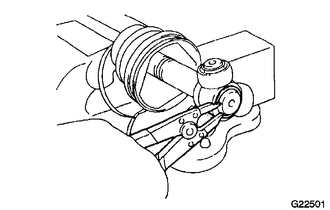
(e) Using a brass bar and hammer, remove the tripod from the outboard joint shaft.
NOTICE:
Do not tap the roller.
(f) Remove the inboard joint boot from the outboard joint shaft.
5. REMOVE FRONT AXLE OUTBOARD JOINT BOOT CLAMP
(a) Using a side cutter, cut the boot clamps.
6. REMOVE OUTBOARD JOINT BOOT
(a) Remove the outboard joint boot from the outboard joint shaft.
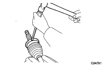
7. REMOVE FRONT DRIVE INNER SHAFT OUTER SHAFT SNAP RING
(a) Using a screwdriver, remove the snap ring.
8. REMOVE FRONT DRIVE SHAFT DUST COVER
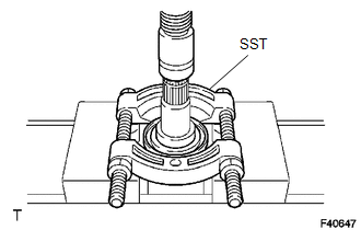
(a) Using SST and a press, remove the dust cover.
SST: 09950-00020
9. REMOVE FRONT AXLE HUB OIL SEAL
(a) Using a screwdriver and a hammer, remove the oil seal.
 Components
COMPONENTS
ILLUSTRATION
ILLUSTRATION
...
 Removal
REMOVAL
PROCEDURE
1. REMOVE FRONT WHEEL
2. DRAIN DIFFERENTIAL OIL
3. SEPARATE FRONT SPEED SENSOR
(a) Remove the bolt and separate the front speed sensor.
(b) Disengage the 2 clamps.
(c) Remov ...
Other materials:
Removal
REMOVAL
PROCEDURE
1. REMOVE NO. 2 ENGINE UNDER COVER SUB-ASSEMBLY (w/ Off Road Package)
2. REMOVE NO. 1 ENGINE UNDER COVER SUB-ASSEMBLY
3. REMOVE FAN AND GENERATOR V BELT
4. DRAIN POWER STEERING FLUID
5. REMOVE FRONT FENDER APRON UPPER SEAL RH
6. DISCONNECT NO. 1 OIL RESERVOIR TO PUMP ...
Meter Illumination does not Dim at Night
DESCRIPTION
In this circuit, the combination meter assembly auto dimmer signals from the
main body ECU using the CAN communication system (CAN V1 Bus). When the combination
meter assembly an auto dimmer signal, it dims the meter illumination (warning and
indicator lights). The main body ECU ( ...
Inspection
INSPECTION
PROCEDURE
1. INSPECT CENTER STOP LIGHT ASSEMBLY (for LED Type Stop Light)
(a) Check the illuminates.
(1) Apply battery voltage to the connector and check the light illumination
condition.
Text in Illustration
*a
Component without ...
