Toyota Tacoma (2015-2018) Service Manual: Installation
INSTALLATION
PROCEDURE
1. INSPECT AND ADJUST BRAKE BOOSTER PUSH ROD
NOTICE:
The brake booster interior must not be a vacuum when adjusting the booster. Stop the engine and depress the brake pedal several times until there is no vacuum in the booster.
HINT:
Adjust the booster push rod when the master cylinder sub-assembly is replaced with a new one. Adjustment is not necessary when the master cylinder sub-assembly is reinstalled and the booster is replaced with a new one.
(a) Apply chalk to the tip of an accessory tool.
HINT:
The accessory tool is enclosed with a new brake master cylinder sub-assembly.
|
(b) Place the accessory tool on the brake booster assembly. |
|
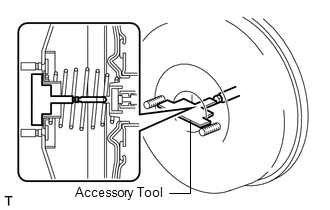
(c) Measure the clearance between the brake booster push rod and accessory tool.
Standard clearance:
0 mm (0 in.)
HINT:
Adjust the clearance in the following cases:
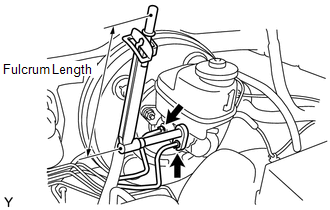
- If there is a clearance between the accessory tool and the shell of the brake booster (floating accessory tool), the push rod is protruding too far.
- If the chalk does not stick on the tip of the brake booster push rod, the push rod protrusion is insufficient.
|
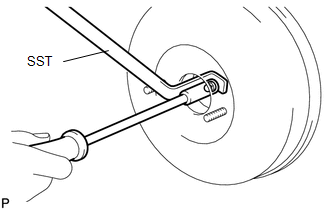
(d) If the clearance is not as specified, adjust the push rod length by holding the rod using SST and turning the tip of the rod using a socket driver (7 mm). SST: 09737-00020 HINT: Check the push rod clearance again after adjustment. |
|
2. INSTALL BRAKE MASTER CYLINDER SUB-ASSEMBLY
(a) Install a new O-ring onto the brake master cylinder sub-assembly.
|
(b) Install the brake master cylinder sub-assembly with the 2 nuts onto the brake booster. Torque: 13 N·m {127 kgf·cm, 9 ft·lbf} |
|
.png)
|
(c) Using a union nut wrench, connect the 2 brake lines to the brake master cylinder sub-assembly. Torque: without union nut wrench : 20 N·m {199 kgf·cm, 14 ft·lbf} with union nut wrench : 18 N·m {187 kgf·cm, 13 ft·lbf} HINT:
|
|
|
(d) Connect the brake fluid level warning switch connector to the brake master cylinder sub-assembly. |
|
.png)
3. INSTALL CLUTCH RESERVOIR TUBE (for Manual Transmission)
|
(a) Connect the clutch reservoir tube to the reservoir. |
|
.png)
4. CONNECT CABLE TO NEGATIVE BATTERY TERMINAL
Torque:
5.4 N·m {55 kgf·cm, 48 in·lbf}
NOTICE:
When disconnecting the cable, some systems need to be initialized after the cable is reconnected.
Click here .gif)
5. FILL RESERVOIR WITH BRAKE FLUID
Click here
6. BLEED MASTER CYLINDER
Click here
7. BLEED BRAKE LINE
Click here
8. BLEED BRAKE ACTUATOR
Click here
9. INSPECT FLUID LEVEL IN RESERVOIR
Click here
10. INSPECT FOR BRAKE FLUID LEAK
11. INSPECT BRAKE PEDAL HEIGHT
Click here
12. INSPECT PEDAL FREE PLAY
Click here
13. INSPECT PEDAL RESERVE DISTANCE
Click here
 Removal
REMOVAL
CAUTION / NOTICE / HINT
NOTICE:
Release the vacuum from booster by depressing the brake pedal several times.
Then remove the brake master cylinder from brake booster.
PROCEDURE
1. PRECAU ...
 Reassembly
REASSEMBLY
PROCEDURE
1. INSTALL MASTER CYLINDER RESERVOIR GROMMET
(a) Apply lithium soap base glycol grease to 2 new grommets.
(b) Install the 2 grommets onto the brake master cylinder reservoir.
...
Other materials:
Key Cannot be Registered
DESCRIPTION
A maximum of 5 master key ID codes can be registered.
WIRING DIAGRAM
Refer to "B2780" (See page )
CAUTION / NOTICE / HINT
NOTICE:
If the transponder key ECU assembly is replaced, refer to Registration (See page
).
PROCEDURE
1.
CHECK REGISTRATIO ...
Power Source Mode does not Change to ON (IG)
DESCRIPTION
If the engine switch is pressed with the electrical key transmitter sub-assembly
in the cabin, the certification ECU (smart key ECU assembly) receives a signal and
changes the power source mode.
HINT:
When the cable is disconnected and reconnected to the negative (-) battery termi ...
Clutch Switch Circuit
DESCRIPTION
Clutch switch circuit inspection is necessary for manual transmission vehicles.
When the clutch pedal is released, the ECM receives the positive (+) battery
voltage through the ECU-IG NO. 2 fuse and ignition switch. While the clutch pedal
is depressed, the clutch switch assembly se ...
