Toyota Tacoma (2015-2018) Service Manual: Components
COMPONENTS
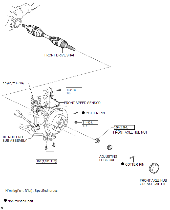
ILLUSTRATION
ILLUSTRATION
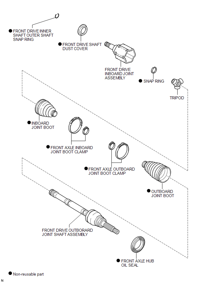

 Disassembly
DISASSEMBLY
PROCEDURE
1. INSPECT FRONT DRIVE SHAFT
(a) Check whether there is no remarkable play in the outboard joint.
(b) Check whether the inboard joint slides smoothly in the thrust directio ...
Other materials:
Diagnostic Trouble Code Chart
DIAGNOSTIC TROUBLE CODE CHART
Sliding Roof (Sliding Roof ECU (Sliding Roof Drive Gear Sub-assembly))
DTC Code
Detection Item
See page
B2341
Sensor (Motor) Failure
B2342
Switch Failure
...
Reassembly
REASSEMBLY
PROCEDURE
1. INSTALL RADIATOR GRILLE MOULDING
(a) Engage the 8 claws to install the radiator grille moulding.
(b) Install the 8 screws.
2. INSTALL NO. 1 RADIATOR GRILLE GARNISH
(a) for Type A and Type B:
(1) Engag ...
Inspection
INSPECTION
PROCEDURE
1. INSPECT TIE ROD END SUB-ASSEMBLY
(a) Flip the ball joint stud back and forth 5 times as shown in the illustration
before installing the nut.
(b) Using a torque wrench, turn the nut continuously at a rate of 2 to 4 seconds
per turn and check the torque reading on the ...
