Toyota Tacoma (2015-2018) Service Manual: Camera Heater
Components
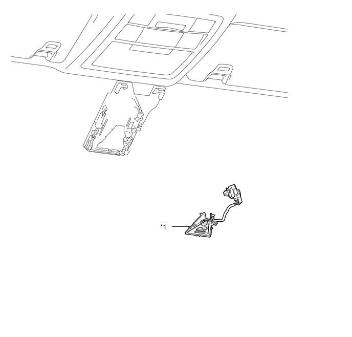
COMPONENTS
ILLUSTRATION
|
*1 |
FORWARD RECOGNITION WITH HEATER HOOD SUB-ASSEMBLY |
- |
- |
Removal
REMOVAL
PROCEDURE
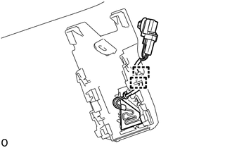
1. REMOVE FORWARD RECOGNITION CAMERA
Click here .gif)
2. REMOVE FORWARD RECOGNITION WITH HEATER HOOD SUB-ASSEMBLY
NOTICE:
Do not touch the internal components of the forward recognition with heater hood sub-assembly or press on the heater when working on the forward recognition with heater hood sub-assembly.
|
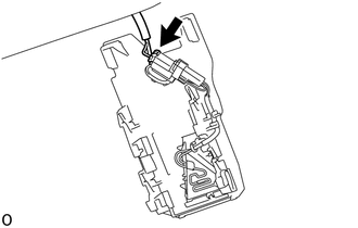
(a) Disconnect the connector. NOTICE: Do not pull the harness forcibly when disconnecting the connector. |
|
|
(b) Disengage the connector clamp. |
|
|
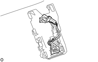
(c) Disengage the 2 guides to disconnect the wire harness. |
|
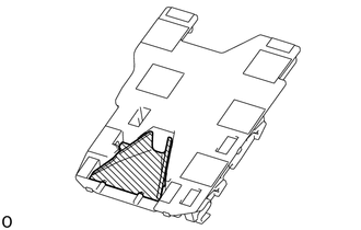
(d) Disengage the claw in the direction indicated by the arrow (1) in the illustration.
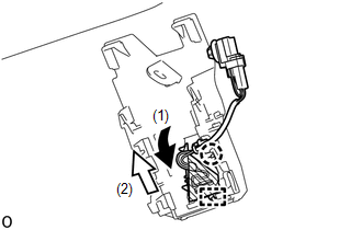
.png) |
Heater Area |
NOTICE:
Do not press the heater area.
(e) Disengage the guide in the direction indicated by the arrow (2) in the illustration to remove the forward recognition with heater hood sub-assembly.
Installation
INSTALLATION
PROCEDURE
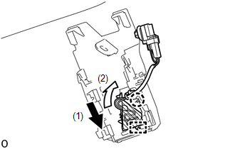
1. INSTALL FORWARD RECOGNITION WITH HEATER HOOD SUB-ASSEMBLY
NOTICE:
Do not touch the internal components of the forward recognition with heater hood sub-assembly or press on the heater when working on the forward recognition with heater hood sub-assembly.
.png)
.png) |
Heater Area |
(a) Engage the guide in the direction indicated by the arrow (1) in the illustration.
(b) Engage the claw in the direction indicated by the arrow (2) in the illustration.
NOTICE:
Do not press the heater area.
|
(c) Engage the 2 guides to connect the wire harness to the forward recognition bracket. |
|
.png)
|
(d) Engage the connector clamp to install the forward recognition with heater hood sub-assembly. |
|
.png)
|
(e) Connect the connector. |
|
.png)
2. INSTALL FORWARD RECOGNITION CAMERA
Click here .gif)
 Cruise Control
...
 Clutch Switch
Components
COMPONENTS
ILLUSTRATION
Removal
REMOVAL
PROCEDURE
1. PRECAUTION
NOTICE:
After turning the engine switch off, waiting time may be required before disconnecting
the cable from ...
Other materials:
Clutch Release Cylinder(for R156f)
Components
COMPONENTS
ILLUSTRATION
Removal
REMOVAL
PROCEDURE
1. DRAIN CLUTCH FLUID
2. REMOVE FRONT PROPELLER SHAFT ASSEMBLY
(See page )
3. DISCONNECT CLUTCH RELEASE CYLINDER TO FLEXIBLE HOSE TUBE
(a) Using a union nut wrench, disconnect the clutch release cylinder
to ...
Operation Check
OPERATION CHECK
1. CHECK REMOTE CONTROL MIRROR FUNCTION
(a) Turn the ignition switch to ON.
(b) With L on the mirror select switch selected, check that the outer rear view
mirror assembly LH surface moves up, down, left and right normally.
(c) With R on the mirror select switch selected, check ...
Installation
INSTALLATION
CAUTION / NOTICE / HINT
CAUTION:
Some of these service operations affect the SRS airbag system. Read the precautionary
notices concerning the SRS airbag system before servicing (See page
).
HINT:
Use the same procedure for both the RH and LH sides.
The procedure des ...
