Toyota Tacoma (2015-2018) Service Manual: Clutch Release Cylinder(for R156f)
Components
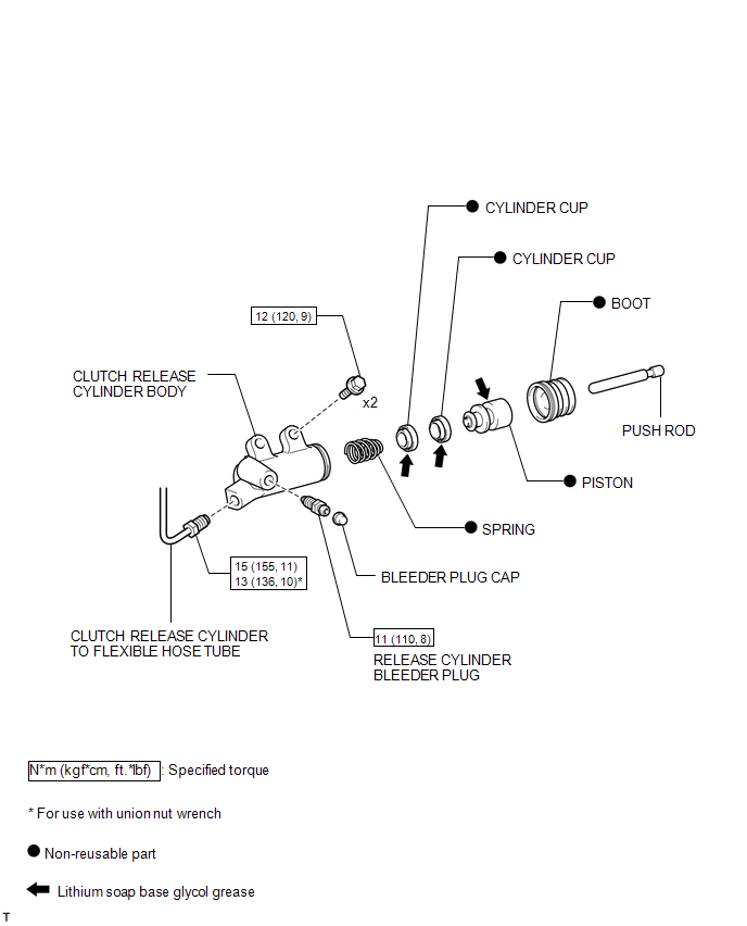
COMPONENTS
ILLUSTRATION
Removal
REMOVAL
PROCEDURE
1. DRAIN CLUTCH FLUID
2. REMOVE FRONT PROPELLER SHAFT ASSEMBLY
(See page .gif) )
)
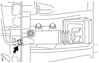
3. DISCONNECT CLUTCH RELEASE CYLINDER TO FLEXIBLE HOSE TUBE
|
(a) Using a union nut wrench, disconnect the clutch release cylinder to flexible hose tube from the clutch release cylinder assembly. HINT: Use a container to catch the fluid. |
|
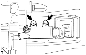
4. REMOVE CLUTCH RELEASE CYLINDER ASSEMBLY
|
(a) Remove the 2 bolts and clutch release cylinder assembly from the manual transmission assembly. |
|
Disassembly
DISASSEMBLY
PROCEDURE
1. REMOVE CLUTCH RELEASE CYLINDER KIT
(a) Remove the boot from the cylinder body.
(b) Remove the push rod from the boot.
|
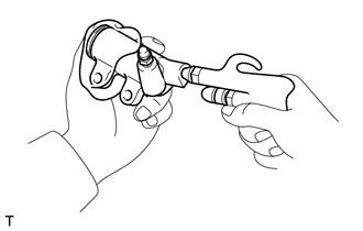
(c) Using compressed air, remove the piston together with the spring from the cylinder body. NOTICE: Do not damage the inside of the cylinder body. |
|
(d) Remove the 2 cylinder cups from the piston.
2. REMOVE RELEASE CYLINDER BLEEDER PLUG
(a) Remove the bleeder plug from the cylinder body.
Installation
INSTALLATION
PROCEDURE
1. INSTALL CLUTCH RELEASE CYLINDER ASSEMBLY
(a) Install the clutch release cylinder assembly to the manual transmission assembly with the 2 bolts.
Torque:
12 N·m {120 kgf·cm, 9 ft·lbf}
2. CONNECT CLUTCH RELEASE CYLINDER TO FLEXIBLE HOSE TUBE
(a) Using a union nut wrench, connect the clutch release cylinder to flexible hose tube to the clutch release cylinder assembly.
Torque:
Specified tightening torque :
15 N·m {155 kgf·cm, 11 ft·lbf}
HINT:
- Calculate the torque wrench reading when changing the fulcrum length
of the torque wrench (See page
.gif) ).
). - When using a union nut wrench (fulcrum length of 22 mm (0.866 in.)) + torque wrench (fulcrum length of 162 mm (6.38 in.)): 13 N*m (136 kgf*cm, 10 ft.*lbf)
3. INSTALL FRONT PROPELLER SHAFT ASSEMBLY
(See page )
4. FILL RESERVOIR WITH BRAKE FLUID
5. BLEED CLUTCH LINE
6. CHECK FLUID LEVEL IN RESERVOIR
7. INSPECT FOR CLUTCH FLUID LEAK
Reassembly
REASSEMBLY
PROCEDURE
1. INSTALL RELEASE CYLINDER BLEEDER PLUG
(a) Install the bleeder plug to the cylinder body.
Torque:
11 N·m {110 kgf·cm, 8 ft·lbf}
2. INSTALL CLUTCH RELEASE CYLINDER KIT
(a) Install 2 new cylinder cups to a new piston.
(b) Install a new spring to the piston.
(c) Apply lithium soap base glycol grease to the portions indicated by the arrows in the illustration.
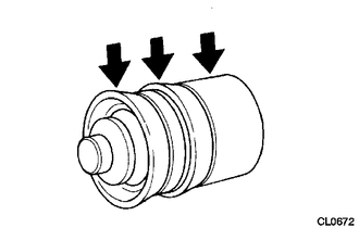 Text in Illustration
.png) |
Lithium soap base glycol grease |
(d) Install the piston (with the spring) to the cylinder body.
NOTICE:
Do not damage the inside of the cylinder body.
(e) Install the push rod to a new boot.
(f) Install the boot (with the push rod) to the cylinder body.
 Clutch Pedal Switch
On-vehicle Inspection
ON-VEHICLE INSPECTION
PROCEDURE
1. CHECK CLUTCH START SYSTEM
(a) Check that the engine does not start when the clutch pedal is released.
(b) Check that the engine starts ...
 Clutch Release Cylinder(for Rc62f)
Components
COMPONENTS
ILLUSTRATION
Disassembly
DISASSEMBLY
PROCEDURE
1. REMOVE CLUTCH RELEASE CYLINDER KIT
(a) Remove the boot from the cylinder body.
(b) Remove the push rod from the bo ...
Other materials:
Lost Communication with ECM (C1437)
DESCRIPTION
The skid control ECU (brake actuator assembly) receives signals from the ECM
via the CAN communication system.
DTC No.
Detection Item
DTC Detection Condition
Trouble Area
C1437
Lost Communication with ECM
...
Precaution
PRECAUTION
1. IGNITION SWITCH EXPRESSION
(a) The type of ignition switch used on this model differs depending on the specifications
of the vehicle. The expressions listed in the table below are used in this section.
Expression
Ignition Switch (Position)
Engine S ...
Installation
INSTALLATION
PROCEDURE
1. INSTALL REAR DIFFERENTIAL DRIVE PINION BEARING SPACER
(a) Install a new front differential drive pinion bearing spacer.
HINT:
Make sure the front differential drive pinion bearing spacer is installed correctly.
2. INSTALL DIFFERENTIAL OIL STORAGE RING
(a) Using a bra ...
