Toyota Tacoma (2015-2018) Service Manual: Clutch Switch
Components
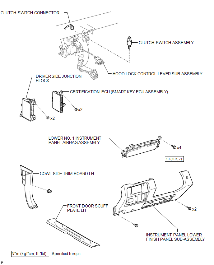
COMPONENTS
ILLUSTRATION
Removal
REMOVAL
PROCEDURE
1. PRECAUTION
NOTICE:
After turning the engine switch off, waiting time may be required before disconnecting the cable from the battery terminal. Therefore, make sure to read the disconnecting the cable from the battery terminal notice before proceeding with work.
Click here .gif)
2. DISCONNECT CABLE FROM NEGATIVE BATTERY TERMINAL
NOTICE:
When disconnecting the cable, some systems need to be initialized after the cable is reconnected.
Click here
3. REMOVE FRONT DOOR SCUFF PLATE LH (for Access Cab)
Click here
4. REMOVE FRONT DOOR SCUFF PLATE LH (for Double Cab)
Click here
5. REMOVE COWL SIDE TRIM BOARD LH
Click here
6. SEPARATE HOOD LOCK CONTROL LEVER SUB-ASSEMBLY
Click here
7. REMOVE INSTRUMENT PANEL LOWER FINISH PANEL SUB-ASSEMBLY
Click here
8. REMOVE LOWER NO. 1 INSTRUMENT PANEL AIRBAG ASSEMBLY
Click here
9. SEPARATE DRIVER SIDE JUNCTION BLOCK
|
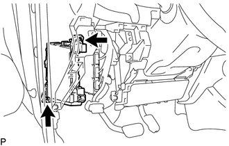
(a) Remove the 2 nuts to separate the driver side junction block. |
|
10. SEPARATE CERTIFICATION ECU (SMART KEY ECU ASSEMBLY) (w/ Smart Key System)
11. REMOVE CLUTCH SWITCH ASSEMBLY
|
(a) Disconnect the connector. |
|
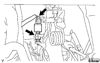
(b) Loosen the nut to remove the clutch switch assembly.
Installation
INSTALLATION
PROCEDURE
1. INSTALL CLUTCH SWITCH ASSEMBLY
(a) Install the clutch switch assembly and tighten the nut.
(b) Connect the connector.
2. INSTALL CERTIFICATION ECU (SMART KEY ECU ASSEMBLY) (w/ Smart Key System)
3. INSTALL LOWER NO. 1 INSTRUMENT PANEL AIRBAG ASSEMBLY
Click here .gif)
4. INSTALL DRIVER SIDE JUNCTION BLOCK
(a) Install the driver side junction block with the 2 nuts.
Torque:
8.0 N·m {82 kgf·cm, 71 in·lbf}
5. INSTALL INSTRUMENT PANEL LOWER FINISH PANEL SUB-ASSEMBLY
Click here
6. INSTALL HOOD LOCK CONTROL LEVER SUB-ASSEMBLY
Click here
7. INSTALL COWL SIDE TRIM BOARD LH
Click here
8. INSTALL FRONT DOOR SCUFF PLATE LH (for Access Cab)
Click here
9. INSTALL FRONT DOOR SCUFF PLATE LH (for Double Cab)
Click here
10. CONNECT CABLE TO NEGATIVE BATTERY TERMINAL
Torque:
5.4 N·m {55 kgf·cm, 48 in·lbf}
NOTICE:
When disconnecting the cable, some systems need to be initialized after the cable is reconnected.
Click here
 Camera Heater
Components
COMPONENTS
ILLUSTRATION
*1
FORWARD RECOGNITION WITH HEATER HOOD SUB-ASSEMBLY
-
-
Removal
REMOVAL
PROCEDURE
1. REMOVE FORWAR ...
 Cruise Control Main Switch
Components
COMPONENTS
ILLUSTRATION
Removal
REMOVAL
PROCEDURE
1. REMOVE STEERING PAD ASSEMBLY
(See page )
2. REMOVE CRUISE CONTROL MAIN SWITCH
(a) Disconnect the connector a ...
Other materials:
Installation
INSTALLATION
CAUTION / NOTICE / HINT
CAUTION:
Be sure to perform this procedure with several people as the transfer assembly
is very heavy.
PROCEDURE
1. INSTALL TRANSFER CASE LOWER PROTECTOR
(a) Install the transfer case lower protector with the 4 bolts.
Torque:
18 N·m {184 kgf·cm, 13 f ...
Open in Rear Floor Electrical Key Oscillator Circuit (B27A6)
DESCRIPTION
The certification ECU (smart key ECU assembly) generates a request signal and
transmits the signal to the No. 2 indoor electrical key antenna assembly (rear floor).
For the No. 2 indoor electrical key antenna assembly (rear floor) to detect when
the electrical key transmitter sub- ...
On-vehicle Inspection
ON-VEHICLE INSPECTION
PROCEDURE
1. INSPECT FLUID LEVEL IN RESERVOIR
(a) Check the fluid level.
If the brake fluid level is lower than the MIN line, check for leaks and inspect
the disc brake pads. If necessary, refill the reservoir with brake fluid to the
MAX line after repair or replaceme ...
