Toyota Tacoma (2015-2018) Service Manual: Antenna Coil Open / Short (B2784)
DESCRIPTION
When an open or short circuit is detected in the antenna coil built into the transponder key coil, the transponder key ECU assembly stores this DTC.
|
DTC No. |
DTC Detection Condition |
Trouble Area |
DTC Output Confirmation Operation |
|---|---|---|---|
|
B2784 |
The antenna coil in the transponder key coil is open/shorted. |
|
Insert the door control transmitter assembly into the ignition key cylinder, turn the ignition switch from off to ON and wait at least 20 seconds. |
|
Vehicle Condition when Malfunction Detected |
Fail-safe Operation when Malfunction Detected |
|---|---|
|
Engine cannot be started |
- |
|
DTC No. |
Data List and Active Test |
|---|---|
|
B2784 |
Antenna Coil Status |
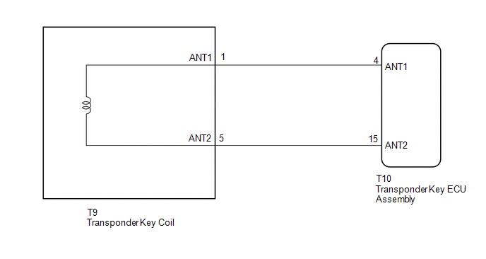
WIRING DIAGRAM
CAUTION / NOTICE / HINT
NOTICE:
- If the transponder key ECU assembly is replaced, refer to Registration
(See page
.gif) ).
). - After repair, confirm that no DTCs are output by performing "DTC Output Confirmation Operation".
PROCEDURE
|
1. |
CLEAR DTC |
(a) Clear the DTCs (See page ).
|
.gif)
|
2. |
CHECK FOR DTC |
(a) Perform "DTC Output Confirmation Operation" procedure.
(b) Check for DTCs (See page ).
OK:
DTC B2784 is not output.
Result|
Result |
Proceed to |
|---|---|
|
DTC B2784 is output |
A |
|
DTC B2784 is not output |
B |
| B | .gif) |
USE SIMULATION METHOD TO CHECK |
|
|
3. |
CHECK CONNECTION OF CONNECTOR |
(a) Check that the connector is properly connected to the transponder key coil.
|
|
4. |
CLEAR DTC |
(a) Clear the DTCs (See page ).
|
|
5. |
CHECK FOR DTC |
(a) Perform "DTC Output Confirmation Operation" procedure.
(b) Check for DTCs. (See page ).
OK:
DTC B2784 is not output.
Result|
Result |
Proceed to |
|---|---|
|
DTC B2784 is not output |
A |
|
DTC B2784 is output |
B |
| A | |
END (CONNECTOR WAS NOT CONNECTED PROPERLY) |
|
|
6. |
CHECK TRANSPONDER KEY COIL (OUTPUT) |
(a) Using an oscilloscope, check the waveform.
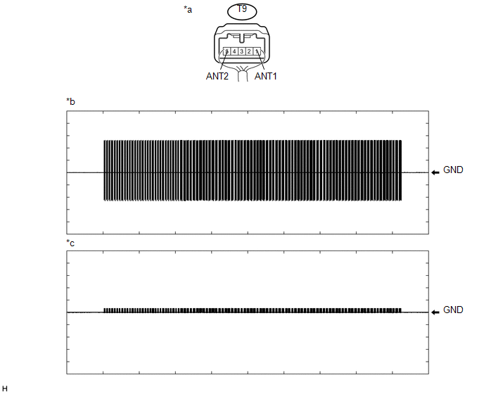 Text in Illustration
|
*a |
Component with harness connected (Transponder Key Coil) |
*b |
Waveform 1 |
|
*c |
Waveform 2 |
- |
- |
Measurement Condition:
|
Tester Connection |
Condition |
Tool Setting |
Specified Condition |
|---|---|---|---|
|
T9-1 (ANT1) - Body ground |
Within 3 seconds of inserting door control transmitter assembly into ignition key cylinder |
2 V/DIV., 500 ms./DIV. |
Pulse generation (See waveform 1) |
|
T9-5 (ANT2) - Body ground |
Within 3 seconds of inserting door control transmitter assembly into ignition key cylinder |
2 V/DIV., 500 ms./DIV. |
Pulse generation (See waveform 2) |
OK:
Waveform is similar to that shown in the illustration.
Result|
Result |
Proceed to |
|---|---|
|
NG |
A |
|
OK |
B |
| B | |
REPLACE TRANSPONDER KEY COIL |
|
|
7. |
CHECK HARNESS AND CONNECTOR (TRANSPONDER KEY ECU ASSEMBLY - TRANSPONDER KEY COIL) |
(a) Disconnect the T10 transponder key ECU assembly connector.
(b) Disconnect the T9 transponder key coil connector.
(c) Measure the resistance according to the value(s) in the table below.
Standard Resistance:
|
Tester Connection |
Condition |
Specified Condition |
|---|---|---|
|
T10-4 (ANT1) - T9-1 (ANT1) |
Always |
Below 1 Ω |
|
T10-15 (ANT2) - T9-5 (ANT2) |
Always |
Below 1 Ω |
|
T10-4 (ANT1) or T9-1 (ANT1) - Body ground |
Always |
10 kΩ or higher |
|
T10-15 (ANT2) or T9-5 (ANT2) - Body ground |
Always |
10 kΩ or higher |
| NG | |
REPAIR OR REPLACE HARNESS OR CONNECTOR |
|
|
8. |
REPLACE TRANSPONDER KEY ECU ASSEMBLY |
(a) Replace the transponder key ECU assembly with a new one (See page
).
NOTICE:
Key ID code registration is necessary when replacing the transponder key ECU
assembly, refer to Registration (See page ).
|
|
9. |
CLEAR DTC |
(a) Clear the DTCs (See page ).
|
|
10. |
CHECK FOR DTC |
(a) Perform "DTC Output Confirmation Operation" procedure.
(b) Check for DTCs (See page ).
OK:
DTC B2784 is not output.
Result|
Result |
Proceed to |
|---|---|
|
DTC B2784 is not output |
A |
|
DTC B2784 is output |
B |
| A | |
END (TRANSPONDER KEY ECU ASSEMBLY WAS DEFECTIVE) |
| B | |
REPLACE TRANSPONDER KEY COIL |
 Push Switch / Key Unlock Warning Switch Malfunction (B2780)
DESCRIPTION
This DTC is stored if the transponder key ECU assembly does not detect that the
unlock warning switch assembly is ON even when the key is in the ignition key cylinder.
Under normal co ...
 Transponder Chip Malfunction (B2793,B2794,B2797,B2798)
DESCRIPTION
DTC B2793 is stored when a malfunction is found in the key during key
code registration or a key code is not registered normally. Replace the
key if key code registration c ...
Other materials:
Terminals Of Ecu
TERMINALS OF ECU
1. ECM
Terminal No. (Symbol)
Wiring Color
Terminal Description
Condition
Specified Condition
E14-20 (TC) - E11-1 (E1)
G - W-B
DTC output signal
Ignition switch ON
...
Open in One Side of Bus 2 Branch Line
DESCRIPTION
When the CAN bus main lines are normal (no open, short to ground, short to +B
or short between lines) and there is an ECU or sensor on the "Communication Bus
Check" screen that is indicated as not communicating or whose connection status
on the "Communication Bus Ch ...
Problem Symptoms Table
PROBLEM SYMPTOMS TABLE
HINT:
Use the table below to help determine the cause of problem symptoms.
If multiple suspected areas are listed, the potential causes of the symptoms
are listed in order of probability in the "Suspected Area" column of the
table. Check each sy ...
