Toyota Tacoma (2015-2018) Service Manual: Air Fuel Ratio Sensor
Components
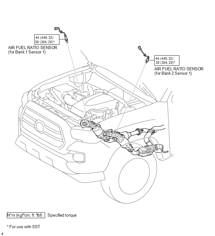
COMPONENTS
ILLUSTRATION
Removal
REMOVAL
PROCEDURE
1. REMOVE AIR FUEL RATIO SENSOR (for Bank 1 Sensor 1)
|
(a) Disconnect the air fuel ratio sensor connector. |
|
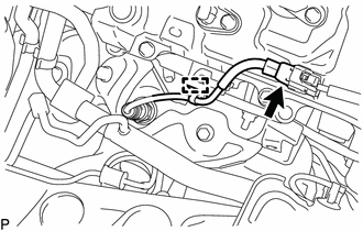
(b) Disengage the clamp to separate the air fuel ratio sensor wire.
|
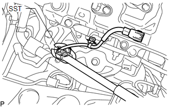
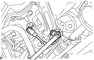
(c) Using SST, remove the air fuel ratio sensor from the exhaust manifold sub-assembly RH. SST: 09224-00011 |
|
2. REMOVE AIR FUEL RATIO SENSOR (for Bank 2 Sensor 1)
|
(a) Disconnect the air fuel ratio sensor connector. |
|
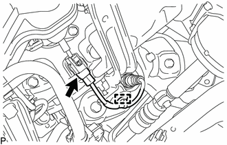
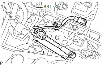
(b) Disengage the clamp to separate the air fuel ratio sensor wire.
|
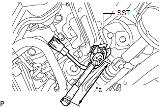
(c) Using SST, remove the air fuel ratio sensor from the exhaust manifold sub-assembly LH. SST: 09224-00011 |
|
Inspection
INSPECTION
PROCEDURE
1. INSPECT AIR FUEL RATIO SENSOR
|
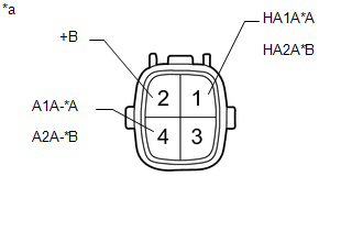
(a) Measure the resistance according to the value(s) in the table below. Text in Illustration
Standard Resistance (for Bank 1 Sensor 1):
Standard Resistance (for Bank 2 Sensor 1):
If the result is not as specified, replace the air fuel ratio sensor. |
|
Installation
INSTALLATION
PROCEDURE
1. INSTALL AIR FUEL RATIO SENSOR (for Bank 1 Sensor 1)
HINT:
Perform "Inspection After Repair" after replacing the air fuel ratio sensor (See
page .gif) ).
).
|
(a) Using SST, install the air fuel ratio sensor to the exhaust manifold sub-assembly RH. Text in Illustration
SST: 09224-00011 Torque: Specified tightening torque : 44 N·m {449 kgf·cm, 32 ft·lbf} HINT:
|
|
(b) Engage the clamp to install the air fuel ratio sensor wire.
(c) Connect the air fuel ratio sensor connector.
2. INSTALL AIR FUEL RATIO SENSOR (for Bank 2 Sensor 1)
HINT:
Perform "Inspection After Repair" after replacing the air fuel ratio sensor (See
page ).
|
(a) Using SST, install the air fuel ratio sensor to the exhaust manifold sub-assembly LH. Text in Illustration
SST: 09224-00011 Torque: Specified tightening torque : 44 N·m {449 kgf·cm, 32 ft·lbf} HINT:
|
|
(b) Engage the clamp to install the air fuel ratio sensor wire.
(c) Connect the air fuel ratio sensor connector.
 Accelerator Pedal
Components
COMPONENTS
ILLUSTRATION
On-vehicle Inspection
ON-VEHICLE INSPECTION
PROCEDURE
1. INSPECT ACCELERATOR PEDAL SENSOR ASSEMBLY
(a) Connect the Techstream to the DLC3.
(b) Turn the ...

Other materials:
Installation
INSTALLATION
CAUTION / NOTICE / HINT
CAUTION:
Some of these service operations affect the SRS airbag system. Read the precautionary
notices concerning the SRS airbag system before servicing (See page
).
HINT:
Use the same procedure for both the RH and LH sides.
The procedure des ...
Back-up Power Source Circuit
DESCRIPTION
The back-up power source circuit for the air conditioning amplifier assembly
is shown below. Power is supplied even when the ignition switch is off. The power
is used for diagnostic trouble code memory, etc.
WIRING DIAGRAM
CAUTION / NOTICE / HINT
NOTICE:
Inspect the fuses for ...
Dtc Check / Clear
DTC CHECK / CLEAR
1. START DIAGNOSTIC MODE
HINT:
Illustrations may differ from the actual vehicle screen depending on
the device settings and options. Therefore, some detailed areas may not
be shown exactly the same as on the actual vehicle screen.
If the system cannot enter d ...
