Toyota Tacoma (2015-2018) Service Manual: Wireless Charger Power Source Circuit
DESCRIPTION
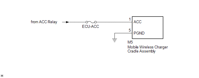
This is the power source circuit to operate the mobile wireless charger cradle assembly.
WIRING DIAGRAM
CAUTION / NOTICE / HINT
NOTICE:
Inspect the fuses for circuits related to this system before performing the following inspection procedure.
PROCEDURE
|
1. |
CHECK HARNESS AND CONNECTOR (MOBILE WIRELESS CHARGER CRADLE ASSEMBLY POWER SOURCE) |
(a) Disconnect the M5 mobile wireless charger cradle assembly connector.
(b) Measure the resistance according to the value(s) in the table below.
Standard Resistance:
|
Tester Connection |
Condition |
Specified Condition |
|---|---|---|
|
M5-5 (PGND) - Body ground |
Always |
Below 1 Ω |
|
M5-1 (ACC) - Body ground |
Always |
10 kΩ or higher |
(c) Measure the voltage according to the value(s) in the table below.
Standard Voltage:
|
Tester Connection |
Switch Condition |
Specified Condition |
|---|---|---|
|
M5-1 (ACC) - M5-5 (PGND) |
Ignition switch ACC |
11 to 14 V |
| OK | .gif) |
PROCEED TO NEXT SUSPECTED AREA SHOWN IN PROBLEM SYMPTOMS TABLE |
| NG | |
REPAIR OR REPLACE HARNESS OR CONNECTOR |
 Terminals Of Ecu
TERMINALS OF ECU
1. MOBILE WIRELESS CHARGER CRADLE ASSEMBLY
Tester Connection
Wiring Color
Terminal Description
Condition
Specified Condition ...
 Main Switch Signal Circuit
DESCRIPTION
When the wireless charger main switch (mobile wireless charger switch) is turned
on, this circuit sends an on signal to the mobile wireless charger cradle assembly
using the power sup ...
Other materials:
Precaution
PRECAUTION
1. EXPRESSIONS OF IGNITION SWITCH
HINT:
The type of ignition switch used on this model differs according to the specifications
of the vehicle. The expressions listed in the table below are used in this section.
Expression
Ignition Switch
(Position)
...
On-vehicle Inspection
ON-VEHICLE INSPECTION
PROCEDURE
1. INSPECT FOR COOLANT LEAK
HINT:
The sliding surface inside the engine water pump assembly is lubricated
by engine coolant. As some engine coolant is discharged during normal operation,
engine coolant residue (solids) may be found on the drain plu ...
System Diagram
SYSTEM DIAGRAM
...
