Toyota Tacoma (2015-2018) Service Manual: Main Switch Signal Circuit
DESCRIPTION
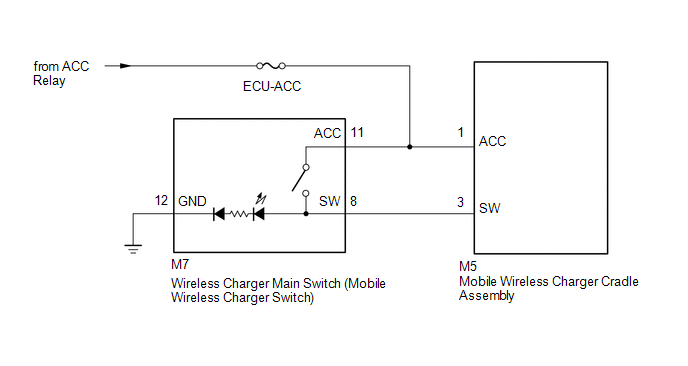
When the wireless charger main switch (mobile wireless charger switch) is turned on, this circuit sends an on signal to the mobile wireless charger cradle assembly using the power supplied to the wireless charger main switch (mobile wireless charger switch).
WIRING DIAGRAM
CAUTION / NOTICE / HINT
NOTICE:
Inspect the fuses for circuits related to this system before performing the following inspection procedure.
PROCEDURE
|
1. |
INSPECT WIRELESS CHARGER MAIN SWITCH (MOBILE WIRELESS CHARGER SWITCH) |
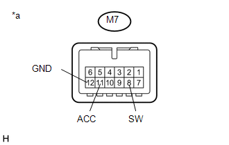
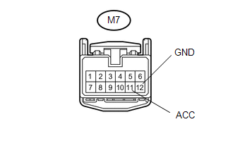
(a) Remove the wireless charger main switch (mobile wireless charger switch)
(See page .gif) ).
).
|
(b) Measure the resistance according to the value(s) in the table below. Standard Resistance:
|
|
| NG | .gif) |
REPLACE WIRELESS CHARGER MAIN SWITCH (MOBILE WIRELESS CHARGER SWITCH) |
|
.gif)
|
2. |
CHECK TERMINAL VOLTAGE (WIRELESS CHARGER MAIN SWITCH - BATTERY AND GROUND) |
|
(a) Measure the voltage and resistance according to the value(s) in the table below. Standard Voltage:
Standard Resistance:
|
|
| NG | |
REPAIR OR REPLACE HARNESS OR CONNECTOR |
|
|
3. |
CHECK HARNESS AND CONNECTOR (WIRELESS CHARGER MAIN SWITCH - MOBILE WIRELESS CHARGER CRADLE ASSEMBLY) |
(a) Disconnect the M5 mobile wireless charger cradle assembly connector.
(b) Measure the resistance according to the value(s) in the table below.
Standard Resistance:
|
Tester Connection |
Condition |
Specified Condition |
|---|---|---|
|
M5-3 (SW) - M7-8 (SW) |
Always |
Below 1 Ω |
| OK | |
PROCEED TO NEXT SUSPECTED AREA SHOWN IN PROBLEM SYMPTOMS TABLE |
| NG | |
REPAIR OR REPLACE HARNESS OR CONNECTOR |
 Wireless Charger Power Source Circuit
DESCRIPTION
This is the power source circuit to operate the mobile wireless charger cradle
assembly.
WIRING DIAGRAM
CAUTION / NOTICE / HINT
NOTICE:
Inspect the fuses for circuits related to t ...
 Status Signal Circuit
DESCRIPTION
This circuit sends a smart key system status signal from the certification ECU
(smart key ECU assembly) to the mobile wireless charger cradle assembly. Based on
this signal, the mobil ...
Other materials:
Installation
INSTALLATION
PROCEDURE
1. INSTALL FRONT SEAT CUSHION HEATER ASSEMBLY (for Driver Side)
(a) Set the front seat cushion heater assembly so that the name stamp side facing
is on the front seat cushion pad side.
(b) Install the front seat cushion heater assembly with 16 new tag pins.
2. INSTALL F ...
Oil Level Sensor
Components
COMPONENTS
ILLUSTRATION
ILLUSTRATION
Inspection
INSPECTION
PROCEDURE
1. INSPECT ENGINE OIL LEVEL SENSOR
(a) Measure the resistance according to the value(s) in the table below.
Standard Resistance:
Tester Connection
Condi ...
Door Unlock Detection Switch Circuit
DESCRIPTION
The main body ECU (multiplex network body ECU) detects the condition of each
door unlock detection switch.
WIRING DIAGRAM
CAUTION / NOTICE / HINT
NOTICE:
If the main body ECU (multiplex network body ECU) is replaced, refer to Registration
(See page ).*1
*1: w/ Smart K ...
