Toyota Tacoma (2015-2018) Service Manual: Front Speed Sensor RH Malfunction (C1401,C1402)
DESCRIPTION
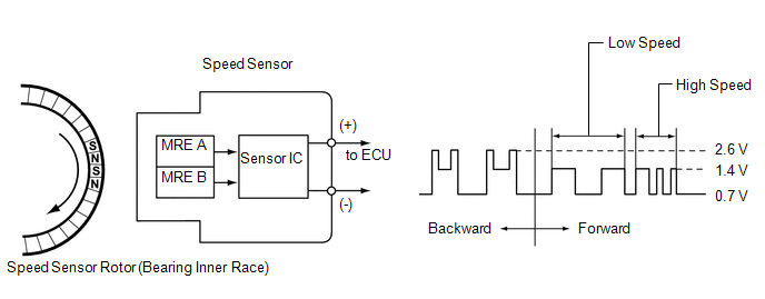
The speed sensor detects wheel speed and sends the appropriate signals to the skid control ECU (brake actuator assembly). These signals are used for brake control.
The speed sensor rotors have rows of alternating N and S magnetic poles and their magnetic fields change when the rotors turn.
Each speed sensor detects that magnetic change and sends a pulse signal to the skid control ECU (brake actuator assembly).
|
DTC No. |
Detection Item |
DTC Detection Condition |
Trouble Area |
|---|---|---|---|
|
C1401 |
Front Speed Sensor RH Malfunction |
Any of the following is detected:
|
|
|
C1402 |
Front Speed Sensor LH Malfunction |
Any of the following is detected:
|
|
HINT:
DTC will be output when conditions for any of the patterns in the table above are met.
PROCEDURE
|
1. |
CHECK FRONT SPEED SENSOR INSTALLATION |
(a) Turn the ignition switch off.
|
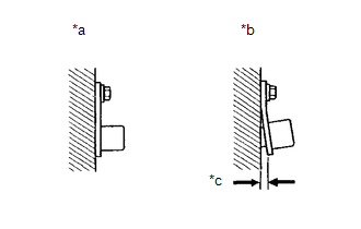
(b) Check the speed sensor installation (See page
OK: There is no clearance between the sensor and the front steering knuckle. The installation bolt is tightened properly. Text in Illustration
|
|
| NG | .gif) |
INSTALL FRONT SPEED SENSOR CORRECTLY |
|
.gif)
|
2. |
INSPECT FRONT SPEED SENSOR TIP |
(a) Remove the front speed sensor (See page .gif) ).
).
(b) Check the speed sensor tip.
OK:
No scratches, oil, or foreign matter on the sensor tip.
NOTICE:
- If no damage to the speed sensor tip is found during this inspection, do not replace the speed sensor.
- If there is iron powder sticking to the rotor, this will result in a malfunction, so confirm that the rotor is not contaminated with foreign material before replacing the sensor.
- Check the speed sensor signal after cleaning or replacement (See page
).
|
Proceed to |
|---|
|
OK |
|
NG |
| NG | |
CLEAN OR REPLACE FRONT SPEED SENSOR |
|
|
3. |
INSPECT FRONT AXLE WITH ABS ROTOR BEARING ASSEMBLY |
(a) Remove the front axle hub inner bearing (See page
).
(b) Check the front skid control rotor.
OK:
No scratches, oil, or foreign matter on the rotors.
NOTICE:
Check the speed sensor signal after cleaning or replacement (See page
).
HINT:
- The front skid control rotor is incorporated into the front axle hub inner bearing.
- If the skid control rotor needs to be replaced, replace it together with the front axle hub inner bearing.
(c) Reinstall the front speed sensor and the front axle hub inner bearing.
- for the front speed sensor: (See page
)
- for the front axle hub inner bearing: (See page
)
| NG | |
CLEAN OR REPLACE FRONT AXLE HUB INNER BEARING |
|
|
4. |
READ VALUE USING TECHSTREAM (FRONT SPEED SENSOR) |
(a) Connect the Techstream to the DLC3.
(b) Start the engine.
(c) Turn the Techstream on.
(d) Enter the following menus: Chassis / ABS/VSC/TRAC / Data List.
(e) According to the display on the Techstream, read the Data List.
ABS/VSC/TRAC|
Tester Display |
Measurement Item |
Normal Condition |
Diagnostic Note |
|---|---|---|---|
|
FR Wheel Speed |
Front wheel speed sensor RH reading/ Min.: 0 km/h (0 mph), Max.: 326 km/h (202 mph) |
Vehicle stopped: 0 km/h (0 mph) |
When driving at constant speed: No large fluctuations |
|
FL Wheel Speed |
Front wheel speed sensor LH reading/ Min.: 0 km/h (0 mph), Max.: 326 km/h (202 mph) |
Vehicle stopped: 0 km/h (0 mph) |
When driving at constant speed: No large fluctuations |
(f) Check that there is no difference between the speed value output from the speed sensor displayed on the Techstream and the speed value displayed on the speedometer when driving the vehicle.
HINT:
Factors that affect the indicated vehicle speed include tire size, tire inflation
and tire wear. The speed indicated on the speedometer has an allowable margin of
error. This can be tested using a speedometer tester (calibrated chassis dynamometer).
For details about testing and the margin of error, see the reference chart (See
page ).
OK:
The speed value output from the speed sensor displayed on the Techstream is the same as the actual vehicle speed measured using a speedometer tester (calibrated chassis dynamometer).
HINT:
If troubleshooting has been carried out according to the Problem Symptoms Table,
refer back to the table and proceed to the next step (See page
).
| OK | |
USE SIMULATION METHOD TO CHECK |
|
|
5. |
REPLACE FRONT SPEED SENSOR |
(a) Turn the ignition switch off.
(b) Replace the front speed sensor (See page
).
NOTICE:
After replacing the speed sensor, perform a Test Mode (signal check) inspection
sensor check (See page
).
|
|
6. |
RECONFIRM DTC |
(a) Clear the DTCs (See page
).
(b) Turn the ignition switch off.
(c) Start the engine.
(d) Drive the vehicle at a speed of 40 km/h (25 mph) or more for at least 60 seconds.
(e) Check if the same DTC is recorded (See page
).
|
Result |
Proceed to |
|---|---|
|
DTCs C1401 and C1402 are not output |
A |
|
DTCs C1401 and/or C1402 are output |
B |
NOTICE:
Check the speed sensor signal after replacement (See page
).
HINT:
- The front skid control rotor is incorporated into the front axle hub inner bearing.
- If the front skid control rotor needs to be replaced, replace it together with the front axle hub inner bearing.
| A | |
END |
| B | |
REPLACE FRONT AXLE HUB INNER BEARING |
 Acceleration Sensor Power Supply Voltage Malfunction (C1381)
DESCRIPTION
The skid control ECU (brake actuator assembly) receives signals from the yaw
rate and acceleration sensor (airbag sensor assembly) via the CAN communication
system.
The airbag sensor ...
 Rear Speed Sensor RH Malfunction (C1403,C1404)
DESCRIPTION
The speed sensor detects wheel speed and sends the appropriate signals to the
skid control ECU (brake actuator assembly). These signals are used for brake control.
The speed sensor rot ...
Other materials:
System Diagram
SYSTEM DIAGRAM
HINT:
Each tire pressure warning valve and transmitter sends its transmitter ID, temperature
and tire pressure information to the tire pressure warning ECU and receiver.
Transmitting ECU (Transmitter)
Receiving ECU
Signal
Communicat ...
All Doors LOCK/UNLOCK Functions do not Operate Via Door Control Switch
DESCRIPTION
The main body ECU (multiplex network body ECU) receives switch signals from the
door control switch assembly on the front passenger door and activates the door
lock motor on each door according to these signals.
WIRING DIAGRAM
PROCEDURE
1.
READ VALUE USIN ...
Reassembly
REASSEMBLY
PROCEDURE
1. INSTALL FRONT AXLE HUB OIL SEAL
(a) Using a brass bar and a hammer, install a new front axle hub oil seal.
NOTICE:
Do not damage the oil seal.
2. INSTALL FRONT AXLE WITH ABS ROTOR BEARING ASSEMBLY
(a) Using SST and a press, install a new bearing onto the front axle ...
