Toyota Tacoma (2015-2018) Service Manual: Wireless Charger Illumination Circuit
DESCRIPTION
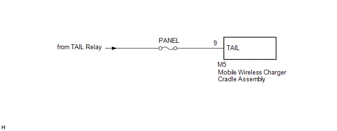
When the light control switch is turned to the tail or head position, this circuit sends an illumination signal to the mobile wireless charger cradle assembly. Based on this signal, the mobile wireless charger cradle assembly dims the indicator lights (green and amber).
WIRING DIAGRAM
CAUTION / NOTICE / HINT
NOTICE:
Inspect the fuses for circuits related to this system before performing the following inspection procedure.
PROCEDURE
|
1. |
CHECK HARNESS AND CONNECTOR (ILLUMINATION SIGNAL) |
(a) Disconnect the M5 mobile wireless charger cradle assembly connector.
(b) Measure the voltage according to the value(s) in the table below.
Standard Voltage:
|
Tester Connection |
Switch Condition |
Specified Condition |
|---|---|---|
|
M5-9 (TAIL) - Body ground |
Light control switch in tail or head position |
11 to 14 V |
| OK | .gif) |
PROCEED TO NEXT SUSPECTED AREA SHOWN IN PROBLEM SYMPTOMS TABLE |
| NG | |
REPAIR OR REPLACE HARNESS OR CONNECTOR |
 Status Signal Circuit
DESCRIPTION
This circuit sends a smart key system status signal from the certification ECU
(smart key ECU assembly) to the mobile wireless charger cradle assembly. Based on
this signal, the mobil ...
 Main Switch Illumination Circuit
DESCRIPTION
When the light control switch is turned to the tail or head position, this circuit
sends an illumination signal to the wireless charger main switch (mobile wireless
charger switch). B ...
Other materials:
Freeze Frame Data
FREEZE FRAME DATA
1. FREEZE FRAME DATA
(a) Using the Techstream, check the vehicle condition (ECU, sensor) when the
brake system operates or a DTC is output.
2. CHECK FREEZE FRAME DATA WHEN BRAKE SYSTEM OPERATES
(a) Freeze frame data is stored when the brake system operates. The freeze frame
...
Components
COMPONENTS
ILLUSTRATION
*1
CHARCOAL CANISTER ASSEMBLY
*2
CHARCOAL CANISTER FUEL HOSE
*3
CHARCOAL CANISTER LEAK DETECTION PUMP SUB-ASSEMBLY
*4
FUEL TANK VENT HOSE
*5
FUEL TANK ...
Unable to Lock Steering Wheel
DESCRIPTION
The steering lock actuator assembly activates the steering lock motor and moves
the lock bar into the steering column to lock the steering.
When the steering lock is operating, the steering may not lock when the lock
bar is not aligned with the lock hole of the steering column. In ...
