Toyota Tacoma (2015-2018) Service Manual: Components
COMPONENTS
ILLUSTRATION
|
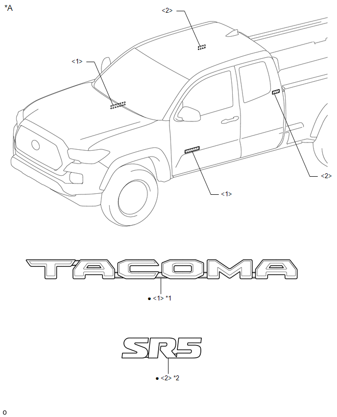
*A |
for Access Cab |
- |
- |
|
*1 |
NO. 1 FRONT DOOR NAME PLATE |
*2 |
NO. 1 ROOF SIDE NAME PLATE |
|
â—Ź |
Non-reusable part |
- |
- |
ILLUSTRATION
|
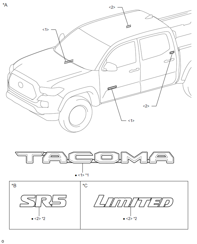
*A |
for Double Cab |
*B |
for Type A |
|
*C |
for Type B |
- |
- |
|
*1 |
NO. 1 FRONT DOOR NAME PLATE |
*2 |
NO. 1 ROOF SIDE NAME PLATE |
|
â—Ź |
Non-reusable part |
- |
- |
ILLUSTRATION
|
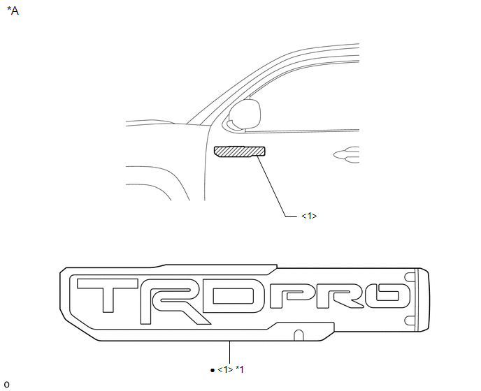
*A |
for LED Fog Light |
- |
- |
|
*1 |
NO. 1 FRONT DOOR NAME PLATE |
- |
- |
|
â—Ź |
Non-reusable part |
- |
- |
ILLUSTRATION
|
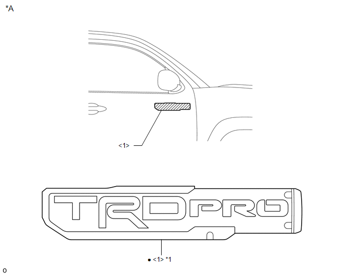
*A |
for LED Fog Light |
- |
- |
|
*1 |
NO. 1 FRONT DOOR NAME PLATE |
- |
- |
|
â—Ź |
Non-reusable part |
- |
- |
ILLUSTRATION
|
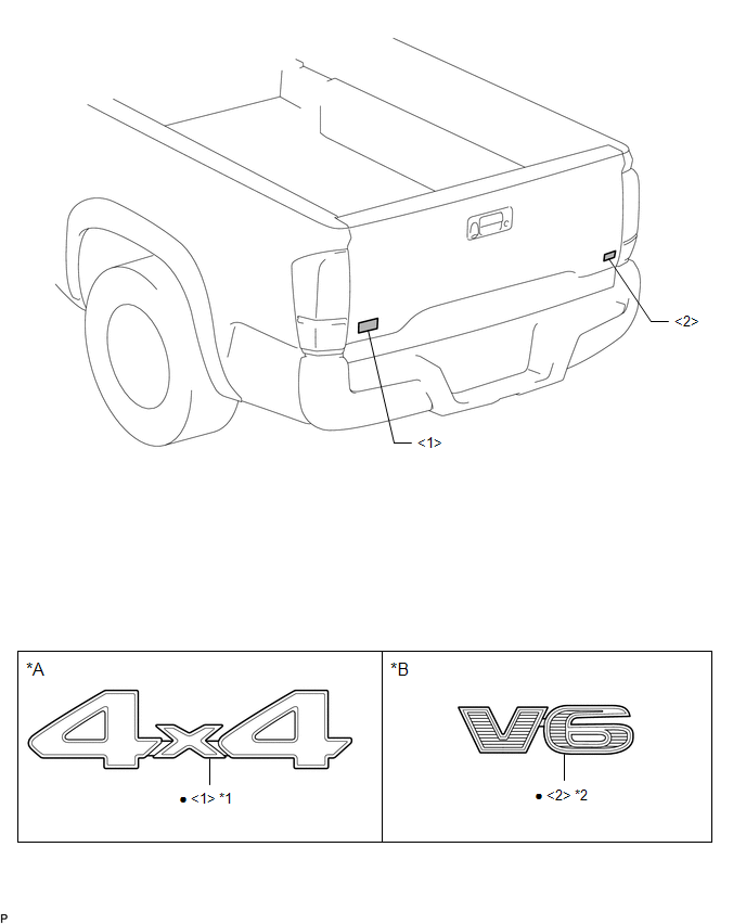
*A |
for 4WD |
*B |
for 2GR-FKS |
|
*1 |
NO. 2 REAR BODY NAME PLATE |
*2 |
NO. 3 REAR BODY NAME PLATE |
|
â—Ź |
Non-reusable part |
- |
- |
ILLUSTRATION
|
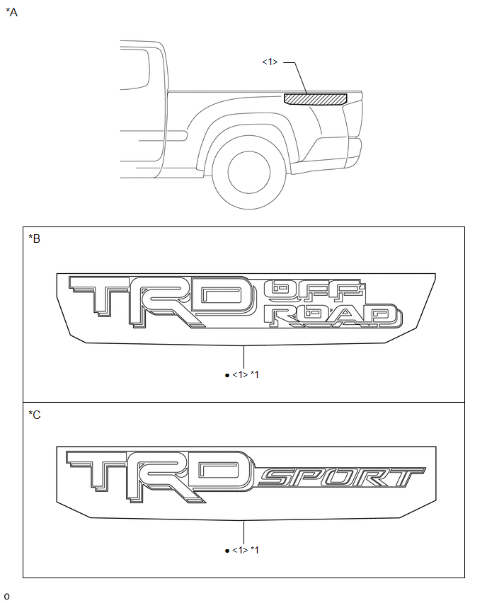
*A |
for 2WD |
*B |
for Type A |
|
*C |
for Type B |
- |
- |
|
*1 |
REAR BODY STRIPE LH |
- |
- |
|
â—Ź |
Non-reusable part |
- |
- |
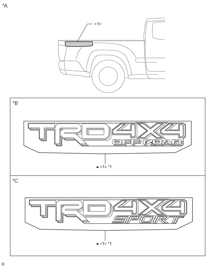
ILLUSTRATION
|
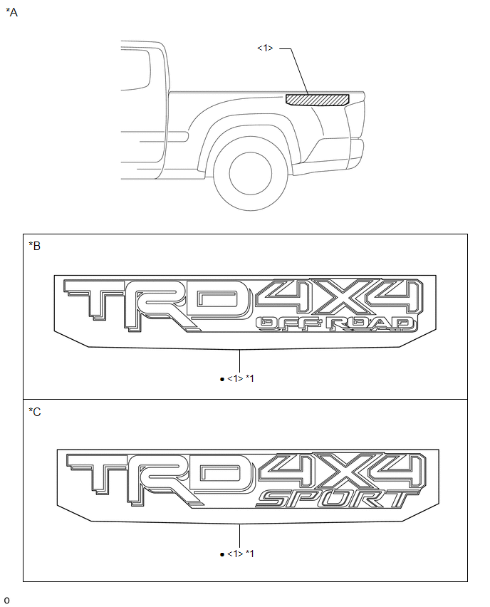
*A |
for 4WD |
*B |
for Type A |
|
*C |
for Type B |
- |
- |
|
*1 |
REAR BODY STRIPE LH |
- |
- |
|
â—Ź |
Non-reusable part |
- |
- |
ILLUSTRATION
|
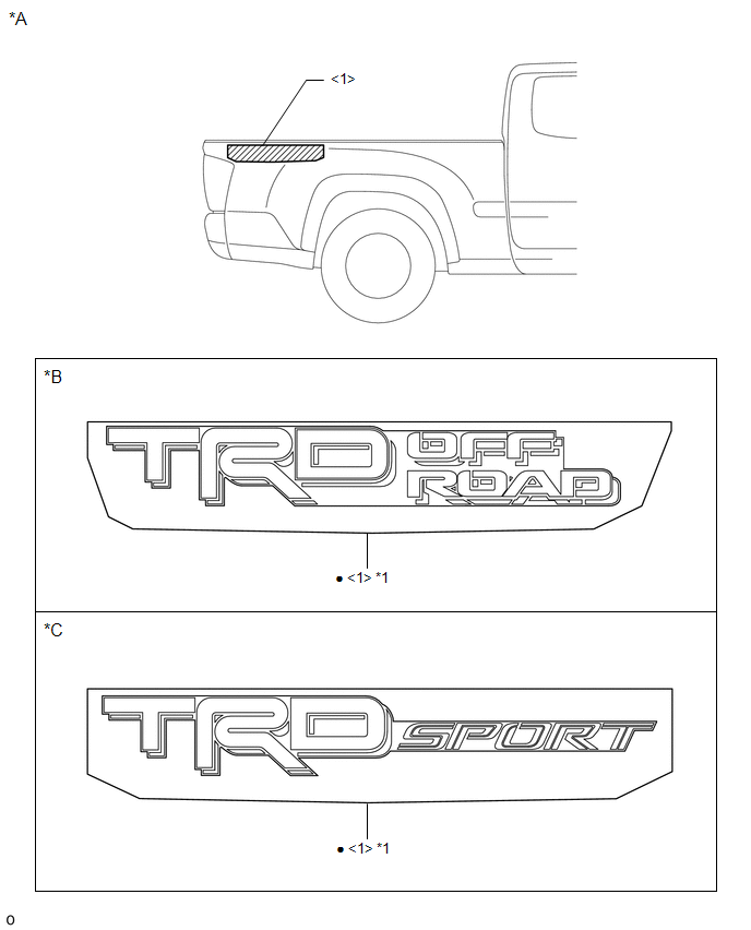
*A |
for 2WD |
*B |
for Type A |
|
*C |
for Type B |
- |
- |
|
*1 |
REAR BODY STRIPE RH |
- |
- |
|
â—Ź |
Non-reusable part |
- |
- |
ILLUSTRATION
|
*A |
for 4WD |
*B |
for Type A |
|
*C |
for Type B |
- |
- |
|
*1 |
REAR BODY STRIPE RH |
- |
- |
|
â—Ź |
Non-reusable part |
- |
- |
 Name Plate
...
 Removal
REMOVAL
CAUTION / NOTICE / HINT
HINT:
When removing the name plates or stripe tapes, heat the vehicle body or tail
gate and name plates or stripe tapes using a heat light.
Heating Temperature
...
Other materials:
A/C ECU Vehicle Information Reading/Writing Processor Malfunction (B15F5)
DESCRIPTION
This DTC is stored when items controlled by the Air conditioning amplifier assembly
cannot be customized via the navigation system vehicle customization screen.
HINT:
The Air conditioning amplifier assembly controls the air conditioning system
related items that are customizable v ...
Detachable pole antenna
The antenna can be removed.
■ Removing the antenna
Place the included wrench around the antenna.
When not in use, the wrench is stored in glove box.
Loosen the antenna with the wrench and remove it.
■ Installing the antenna
Tighten the antenna by one hand until it will not t ...
Steering Angle Sensor (C1A47)
DESCRIPTION
The forward recognition camera receives steering angle information from the spiral
cable with sensor sub-assembly. If the forward recognition camera detects a spiral
cable with sensor sub-assembly malfunction, DTC C1A47 is stored.
DTC No.
Detection Item
...
