Toyota Tacoma (2015-2018) Service Manual: Status Signal Circuit
DESCRIPTION
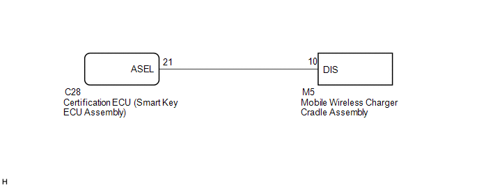
This circuit sends a smart key system status signal from the certification ECU (smart key ECU assembly) to the mobile wireless charger cradle assembly. Based on this signal, the mobile wireless charger cradle assembly suspends or resumes wireless charging.
WIRING DIAGRAM
CAUTION / NOTICE / HINT
NOTICE:
Before replacing the certification ECU (smart key ECU assembly), refer to the
Registration ( .gif) ).
).
PROCEDURE
|
1. |
INSPECT MOBILE WIRELESS CHARGER CRADLE ASSEMBLY |
|
(a) Measure the voltage according to the value(s) in the table below. Text in Illustration
Standard Voltage:
HINT:
|
|
| OK | .gif) |
PROCEED TO NEXT SUSPECTED AREA SHOWN IN PROBLEM SYMPTOMS TABLE |
|
.gif)
|
2. |
CHECK HARNESS AND CONNECTOR (MOBILE WIRELESS CHARGER CRADLE ASSEMBLY - CERTIFICATION ECU (SMART KEY ECU ASSEMBLY)) |
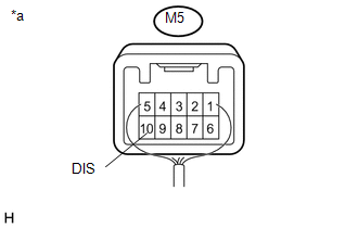
(a) Disconnect the M5 mobile wireless charger cradle assembly connector.
(b) Disconnect the C28 certification ECU (smart key ECU assembly) connector.
(c) Measure the resistance according to the value(s) in the table below.
Standard Resistance:
|
Tester Connection |
Condition |
Specified Condition |
|---|---|---|
|
M5-10 (DIS) - C28-21 (ASEL) |
Always |
Below 1 Ω |
|
M5-10 (DIS) - Body ground |
Always |
10 kΩ or higher |
| OK | |
REPLACE CERTIFICATION ECU (SMART KEY ECU ASSEMBLY) |
| NG | |
REPAIR OR REPLACE HARNESS OR CONNECTOR |
 Main Switch Signal Circuit
DESCRIPTION
When the wireless charger main switch (mobile wireless charger switch) is turned
on, this circuit sends an on signal to the mobile wireless charger cradle assembly
using the power sup ...
 Wireless Charger Illumination Circuit
DESCRIPTION
When the light control switch is turned to the tail or head position, this circuit
sends an illumination signal to the mobile wireless charger cradle assembly. Based
on this signal, t ...
Other materials:
Reassembly
REASSEMBLY
PROCEDURE
1. INSPECT CENTER NO. 2 SUPPORT BEARING ASSEMBLY
(a) Turn the center bearing by hand, check that it turns smoothly without catching
and that there are no cracks or damage.
If there are any defects, replace it.
2. INSTALL CENTER NO. 2 SUPPORT BEARING ASSEMBLY
(a) Instal ...
Automatic Disconnecting Differential Motor Limit Switch Circuit (P17A4)
DESCRIPTION
When the A.D.D. actuator switches between 2WD and 4WD, the DL1 and DL2 terminals
of the limit switch and ADD terminal of the A.D.D. position switch change to one
of the following ON/OFF combinations listed in the table below.
Terminal
In 2WD
Switchi ...
Precaution
PRECAUTION
1. IGNITION SWITCH EXPRESSION
HINT:
The type of ignition switch used on this model differs depending on the specifications
of the vehicle. The expressions listed in the table below are used in this section.
Expression
Ignition Switch (Position)
Engin ...
