Toyota Tacoma (2015-2018) Service Manual: Wireless Charger Assembly
Components
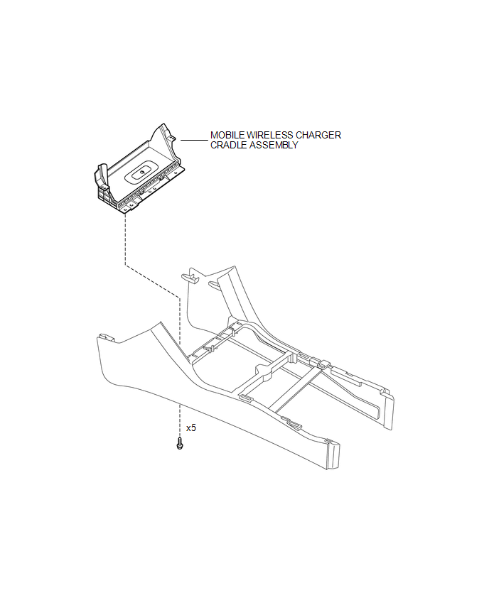
COMPONENTS
ILLUSTRATION
Removal
REMOVAL
PROCEDURE
1. REMOVE FRONT CONSOLE BOX
(See page .gif) )
)
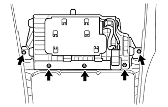
2. REMOVE MOBILE WIRELESS CHARGER CRADLE ASSEMBLY
|
(a) Remove the 5 screws and mobile wireless charger cradle assembly. |
|
Installation
INSTALLATION
PROCEDURE
1. INSTALL MOBILE WIRELESS CHARGER CRADLE ASSEMBLY
(a) Install the mobile wireless charger cradle assembly with the 5 screws.
2. INSTALL FRONT CONSOLE BOX
(See page .gif) )
)
 Voltage Inverter
Components
COMPONENTS
ILLUSTRATION
Inspection
INSPECTION
PROCEDURE
1. INSPECT VOLTAGE INVERTER ASSEMBLY
(a) Check the voltage inverter assembly.
(1) Measure the voltage according to the ...
 Wireless Charger Main Switch
Components
COMPONENTS
ILLUSTRATION
Removal
REMOVAL
PROCEDURE
1. REMOVE INSTRUMENT PANEL LOWER CENTER FINISH PANEL
(See page )
2. REMOVE MOBILE WIRELESS CHARGER SWITCH
(a) Di ...
Other materials:
Short to +B in Outer Mirror Indicator(Slave) (C1AB1)
DESCRIPTION
This DTC is stored when the blind spot monitor sensor RH detects a +B short in
the blind spot monitor indicator RH.
DTC Code
DTC Detection Condition
Trouble Area
C1AB1
With the blind spot monitor main switch assembly (warni ...
Diagnosis System
DIAGNOSIS SYSTEM
1. DESCRIPTION
The ECU stores trouble codes when malfunctions occur.
The diagnostic system allows for reading of the trouble codes from the DLC3.
Use the Techstream to help diagnose and repair the problem.
2. CHECK DLC3
(a) Check the DLC3 (See page ).
3. INSPECT BATTERY VOLT ...
Open or Short Circuit in Back Camera Signal (C1622)
DESCRIPTION
This DTC is stored if the radio and display receiver assembly*1 or navigation
receiver assembly*2 judges as a result of its self check that the signals or signal
lines between the radio and display receiver assembly*1 or navigation receiver assembly*2
and the rear television camer ...
