Toyota Tacoma (2015-2018) Service Manual: Wireless Charger Main Switch
Components
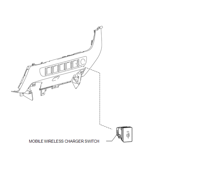
COMPONENTS
ILLUSTRATION
Removal
REMOVAL
PROCEDURE
1. REMOVE INSTRUMENT PANEL LOWER CENTER FINISH PANEL
(See page .gif) )
)
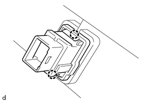
2. REMOVE MOBILE WIRELESS CHARGER SWITCH
|
(a) Disengage the 2 claws to remove the mobile wireless charger switch. |
|
Inspection
INSPECTION
PROCEDURE
1. INSPECT MOBILE WIRELESS CHARGER SWITCH
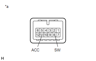
(a) Check the mobile wireless charger switch.
|
(1) Measure the resistance according to the value(s) in the table below. Standard Resistance:
If the result is not as specified, replace the mobile wireless charger switch. |
|
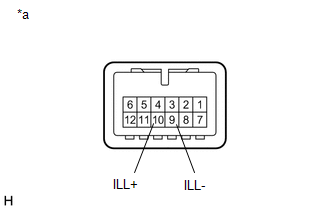
(b) Check that the switch indicator light illuminates.
|
(1) Apply battery voltage to the mobile wireless charger switch connector and check the operation of the switch indicator light. OK:
If the result is not as specified, replace the mobile wireless charger switch. |
|
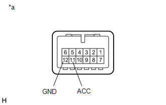
(c) Check that the switch illuminates.
|
(1) Apply battery voltage to the mobile wireless charger switch and check that the switch illuminates. OK:
If the result is not as specified, replace the mobile wireless charger switch. |
|
Installation
INSTALLATION
PROCEDURE
1. INSTALL MOBILE WIRELESS CHARGER SWITCH
(a) Engage the 2 claws to install the mobile wireless charger switch.
2. INSTALL INSTRUMENT PANEL LOWER CENTER FINISH PANEL
(See page .gif) )
)
 Wireless Charger Assembly
Components
COMPONENTS
ILLUSTRATION
Removal
REMOVAL
PROCEDURE
1. REMOVE FRONT CONSOLE BOX
(See page
)
2. REMOVE MOBILE WIRELESS CHARGER CRADLE ASSEMBLY
(a) Remove the 5 sc ...

Other materials:
Reassembly
REASSEMBLY
PROCEDURE
1. INSTALL REAR AXLE HUB BOLT
(a) Install a new deflector gasket and deflector onto the rear axle shaft.
HINT:
Align the 2 notches.
(b) Install the 6 bolts through the axle hub.
...
Pump Motor Relay (C1253)
DESCRIPTION
The motor relay (semiconductor relay) is built into the master cylinder solenoid
and drives the pump motor based on a signal from the skid control ECU (master cylinder
solenoid).
DTC No.
DTC Detecting Condition
Trouble Areas
C1253
...
Ecm
Components
COMPONENTS
ILLUSTRATION
ILLUSTRATION
Installation
INSTALLATION
PROCEDURE
1. INSTALL NO. 2 ECM BRACKET
(a) Install the No. 2 ECM bracket to the ECM with the 2 screws.
Torque:
3.2 N·m {33 kgf·cm, 28 in·lbf}
2. INSTALL ECM BRACKET
(a) Install the ECM bracket to the EC ...
