Toyota Tacoma (2005–2015) Owners Manual: What to do if...
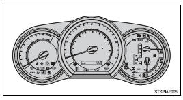
■ Instrument cluster
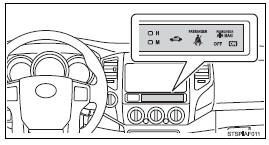
■ Center panel
■Warning lights
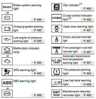
*1: Slip indicator comes on.
*2: The indicator flashes to indicate a malfunction.
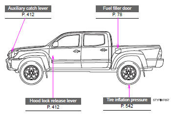
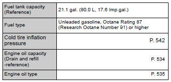
GAS STATION INFORMATION
 Camper information
This information has been prepared in accordance with regulation issued by
the National Highway Traffic Safety Administration of the U.S. Department of Transportation.
It provides the purchasers a ...
Other materials:
Center Airbag Sensor Communication Stop Mode
DESCRIPTION
Detection Item
Symptom
Trouble Area
Center Airbag Sensor Communication Stop Mode
Either condition is met:
Communication stop for "Airbag" is indicated on the "Communication
Bus Check" sc ...
Removal
REMOVAL
PROCEDURE
1. REMOVE LOWER STEERING COLUMN COVER
2. REMOVE UPPER STEERING COLUMN COVER
3. REMOVE WINDSHIELD WIPER SWITCH ASSEMBLY
(a) Disconnect the 2 connectors.
Text in Illustration
*a
Protective Tape
...
Steering Angle Sensor Output Malfunction (C1434)
DESCRIPTION
Steering angle sensor (spiral cable with sensor sub-assembly) signals are sent
to the skid control ECU (master cylinder solenoid) via the CAN communication system.
When there is a malfunction in the CAN communication system, it is detected by the
steering angle sensor (spiral cabl ...
