Toyota Tacoma (2015-2018) Service Manual: Reassembly
REASSEMBLY
PROCEDURE
1. INSTALL UN-LOCK WARNING SWITCH ASSEMBLY (w/o Smart Key System)
(a) Engage the 2 claws to install the un-lock warning switch assembly to the upper steering column bracket assembly.
2. INSTALL IGNITION SWITCH LOCK CYLINDER ASSEMBLY (w/o Smart Key System)
|
(a) Turn the ignition switch to ACC. |
|
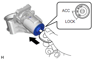
(b) Install the ignition switch lock cylinder assembly to the upper steering column bracket assembly.
(c) Make sure that the ignition switch lock cylinder assembly is securely installed into the upper steering column bracket assembly.
3. INSTALL KEY INTER LOCK SOLENOID (for Automatic Transmission without Smart Key System)
(a) Engage the claw to install the key interlock solenoid to the upper steering column bracket assembly.
(b) Install the screw.
4. INSTALL IGNITION OR STARTER SWITCH ASSEMBLY (w/o Smart Key System)
(a) Install the ignition or starter switch assembly to the upper steering column bracket assembly with the 2 screws.
5. INSTALL TRANSPONDER KEY AMPLIFIER (w/o Smart Key System)
(a) Engage the 2 claws to install the transponder key amplifier.
6. INSPECT STEERING LOCK OPERATION (w/o Smart Key System)
(a) Check that the steering mechanism is activated when removing the key.
(b) Check that the steering mechanism is deactivated when inserting the key and turning it to ACC position.
7. INSTALL UPPER STEERING COLUMN BRACKET WITH SWITCH ASSEMBLY (w/o Smart Key System)
|
(a) Secure the steering column assembly in a vise between aluminum plates. NOTICE: Do not overtighten the vise. |
|
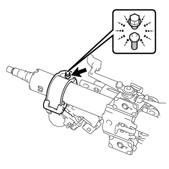
(b) Temporarily install the upper steering column bracket with switch assembly with a new tapered-head bolt.
(c) Tighten the tapered-head bolt until the bolt head breaks off.
8. INSTALL STEERING LOCK ACTUATOR ASSEMBLY (w/ Smart Key System)
HINT:
- Perform the same procedure as for the upper steering column bracket with switch assembly.
- When replacing the steering lock actuator assembly, perform initialization
(See page
.gif) ).
).
9. INSTALL STEERING INTERMEDIATE SHAFT ASSEMBLY
.png)
(a) Align the matchmarks on the steering intermediate shaft assembly and steering main shaft assembly.
(b) Install the steering intermediate shaft sub-assembly with the bolt.
Torque:
35 N·m {357 kgf·cm, 26 ft·lbf}
 Installation
INSTALLATION
PROCEDURE
1. INSTALL STEERING COLUMN ASSEMBLY
(a) Install the steering column assembly with the 2 nuts and bolt.
Torque:
21 N·m {214 kgf·cm, 15 ft·lbf}
(b) Connect each of the c ...

Other materials:
Data List / Active Test
DATA LIST / ACTIVE TEST
1. DATA LIST
HINT:
Using the Techstream to read the Data List allows the values or states of switches,
sensors, actuators and other items to be read without removing any parts. This non-intrusive
inspection can be very useful because intermittent conditions or signals ...
Radio Antenna Cord
Components
COMPONENTS
ILLUSTRATION
Removal
REMOVAL
PROCEDURE
1. REMOVE INSTRUMENT PANEL SUB-ASSEMBLY
(See page )
2. REMOVE ANTENNA CORD SUB-ASSEMBLY
(a) Disengage the 4 clamps to remove the antenna cord sub-assembly.
Installation
INSTALLATION
PROCEDURE
1. INSTALL ANTENNA COR ...
Fail-safe Chart
FAIL-SAFE CHART
FAIL-SAFE FUNCTION
(a) When a malfunction occurs in the pre-collision system, a message will be
displayed on the multi-information display and the pre-collision system will be
disabled depending on the malfunction.
Warning Message
Cause
DTC No. ...
