Toyota Tacoma (2015-2018) Service Manual: Inspection
INSPECTION
PROCEDURE
1. INSPECT WATER INLET WITH THERMOSTAT SUB-ASSEMBLY
HINT:
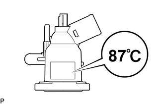
The valve opening temperature is inscribed on the water inlet with thermostat sub-assembly.
(a) Immerse the thermostat in the water, then heat the water gradually.
CAUTION:
- Do not your hands into the water that has been heated for the inspection.
- Touching the heated water could result in burns.
(b) Check the valve opening temperature of the water inlet with thermostat sub-assembly.
Standard valve opening temperature:
85 to 89°C (185 to 192°F)
NOTICE:
When checking the water inlet with thermostat sub-assembly in water, keep the terminals dry. After the check, wipe the water inlet with thermostat sub-assembly dry.
If the valve opening temperature is not as specified, replace the water inlet with thermostat sub-assembly.
|
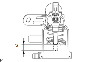
(c) Check the valve lift. Text in Illustration
Standard valve lift: 8.0 mm (0.315 in.) or more at 100°C (212°F) If the valve lift is not as specified, replace the water inlet with thermostat sub-assembly. |
|
(d) Check that the valve is fully closed when the water inlet with thermostat sub-assembly is at a low temperature (below 40°C (104°F)).
If the valve is not fully closed, replace the water inlet with thermostat sub-assembly.
(e) Measure the resistance according to the value(s) in the table below.
Standard Resistance:
|
Tester Connection |
Condition |
Specified Condition |
|---|---|---|
|
1 - 2 |
20°C (68°F) |
10.54 to 14.26 Ω |
If the result is not as specified, replace the water inlet with thermostat sub-assembly.
 Removal
REMOVAL
PROCEDURE
1. REMOVE NO. 2 ENGINE UNDER COVER SUB-ASSEMBLY (w/ Off Road Package)
2. REMOVE NO. 1 ENGINE UNDER COVER SUB-ASSEMBLY
3. DRAIN ENGINE COOLANT
4. REMOVE V-BANK COVER SUB-ASSEM ...
 Installation
INSTALLATION
PROCEDURE
1. INSTALL WATER INLET WITH THERMOSTAT SUB-ASSEMBLY
(a) Install a new gasket to the water inlet with thermostat sub-assembly.
(b) Install the water inlet with thermostat sub ...
Other materials:
Removal
REMOVAL
CAUTION / NOTICE / HINT
CAUTION:
Some of these service operations affect the SRS airbag system. Read the precautionary
notices concerning the SRS airbag system before servicing (See page
).
HINT:
Use the same procedure for both the RH and LH sides.
The procedure describe ...
Dtc Check / Clear
DTC CHECK / CLEAR
1. CHECK DTC
(a) Connect the Techstream to the DLC3.
(b) Turn the ignition switch to ON.
(c) Turn the blind spot monitor main switch assembly (warning canceling switch
assembly) on.
(d) Turn the Techstream on.
(e) Enter the following menus: Body Electrical / Blind Spot Moni ...
ECU Power Source Circuit
WIRING DIAGRAM
CAUTION / NOTICE / HINT
NOTICE:
Inspect the fuses for circuits related to this system before performing the following
inspection procedure.
PROCEDURE
1.
INSPECT BATTERY
(a) Check the battery voltage.
Standard voltage:
11 to 14 V
NG
...
