Toyota Tacoma (2015-2018) Service Manual: Lost Communication with Front Panel LIN (B14B2)
DESCRIPTION
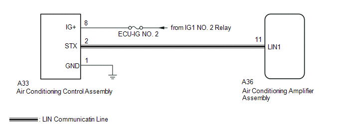
The air conditioning control assembly communicates with the air conditioning amplifier assembly through the LIN communication system.
If the LIN communication system malfunctions, the air conditioning amplifier assembly does not operate even if the air conditioning control assembly is operated.
|
DTC No. |
DTC Detection Condition |
Trouble Area |
|---|---|---|
|
B14B3 |
Lost communication with the air conditioning control assembly. |
|
WIRING DIAGRAM
CAUTION / NOTICE / HINT
NOTICE:
Inspect the fuses for circuits related to this system before performing the following inspection procedure.
PROCEDURE
|
1. |
CHECK HARNESS AND CONNECTOR (AIR CONDITIONING CONTROL ASSEMBLY - POWER SOURCE CIRCUIT) |
(a) Disconnect the A33 air conditioning control assembly connector.
(b) Measure the voltage according to the value(s) in the table below.
Standard Voltage:
|
Tester Connection |
Switch Condition |
Specified Condition |
|---|---|---|
|
A33-8 (IG+) - Body ground |
Ignition switch off |
Below 1 V |
|
A33-8 (IG+) - Body ground |
Ignition switch ON |
11 to 14 V |
(c) Measure the resistance according to the value(s) in the table below.
Standard Resistance:
|
Tester Connection |
Condition |
Specified Condition |
|---|---|---|
|
A33-1 (GND) - Body ground |
Always |
Below 1 Ω |
| NG | .gif) |
REPAIR OR REPLACE HARNESS OR CONNECTOR |
|
.gif)
|
2. |
CHECK HARNESS AND CONNECTOR (AIR CONDITIONING CONTROL ASSEMBLY - AIR CONDITIONING AMPLIFIER ASSEMBLY) |
(a) Disconnect the A33 air conditioning control assembly connector.
(b) Disconnect the A36 air conditioning amplifier assembly connector.
(c) Measure the resistance according to the value(s) in the table below.
Standard Resistance:
|
Tester Connection |
Condition |
Specified Condition |
|---|---|---|
|
A33-2 (STX) - A36-11 (LIN1) |
Always |
Below 1 Ω |
|
A33-2 (STX) or A36-11 (LIN1) - Body ground |
Always |
10 kΩ or higher |
| NG | |
REPAIR OR REPLACE HARNESS OR CONNECTOR |
|
|
3. |
REPLACE AIR CONDITIONING CONTROL ASSEMBLY |
(a) Replace the air conditioning control assembly (See page
.gif) ).
).
HINT:
Since the air conditioning control assembly cannot be inspected while it is removed from the vehicle, replace the air conditioning control assembly with a new or known good one and same problem occurs again.
OK:
Same problem does not occurs.
|
Result |
Proceed to |
|---|---|
|
OK |
A |
|
NG (When troubleshooting according to Problem Symptoms Table) |
B |
|
NG (When troubleshooting according to the DTC) |
C |
| A | |
END (AIR CONDITIONING CONTROL ASSEMBLY WAS DEFECTIVE) |
| B | |
PROCEED TO NEXT SUSPECTED AREA SHOWN IN PROBLEM SYMPTOMS TABLE |
| C | |
REPLACE AIR CONDITIONING AMPLIFIER ASSEMBLY |
 Dtc Check / Clear
DTC CHECK / CLEAR
1. DTC CHECK USING TECHSTREAM
(a) Connect the Techstream to the DLC3.
(b) Turn the ignition switch to ON.
(c) Turn the Techstream on.
(d) Enter the following menus: Body Electri ...
 Air Mix Damper Control Servo Motor Circuit (Driver Side) (B1446/46)
DESCRIPTION
This No. 3 air conditioning radiator damper servo sub-assembly (for driver side
air mix) is controlled by the air conditioning amplifier assembly and moves the
air mix damper (for dri ...
Other materials:
Invalid Data Received from Deceleration Sensor (C1442,C1443)
DESCRIPTION
The skid control ECU (master cylinder solenoid) receives signals from the yaw
rate and acceleration sensor (airbag sensor assembly) via the CAN communication
system.
The airbag sensor assembly has a built-in yaw rate and acceleration sensor.
DTC Code
DTC Dete ...
Air Mix Damper Control Servo Motor Circuit (Driver Side) (B1446/46)
DESCRIPTION
This No. 3 air conditioning radiator damper servo sub-assembly (for driver side
air mix) is controlled by the air conditioning amplifier assembly and moves the
air mix damper (for driver side) to the desired position.
DTC No.
DTC Detection Condition
...
Fuel Main Valve
Components
COMPONENTS
ILLUSTRATION
Removal
REMOVAL
PROCEDURE
1. REMOVE FUEL SUCTION TUBE WITH PUMP AND GAUGE ASSEMBLY
(See page )
2. REMOVE FUEL SENDER GAUGE ASSEMBLY
3. REMOVE NO. 1 FUEL SUB-TANK
4. REMOVE FUEL PUMP FILTER
5. REMOVE FUEL MAIN VALVE ASSEMBLY
(a) Remove t ...
