Toyota Tacoma (2015-2018) Service Manual: Replacement
REPLACEMENT
PROCEDURE
1. REPLACE INTAKE VALVE GUIDE BUSH
(a) Heat the cylinder head to 80 to 100°C (176 to 212°F).
(b) Place the cylinder head on wooden blocks.
|
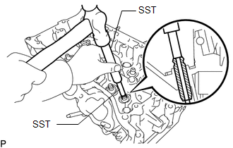
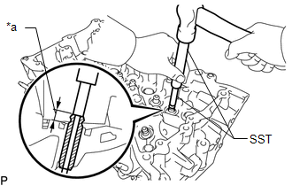
(c) Using SST and a hammer, tap out the intake valve guide bushes. SST: 09201-10000 09201-01050 SST: 09950-70010 09951-07100 |
|
(d) Using a caliper gauge, measure the intake valve guide bush bore diameter of the cylinder head.
Standard cylinder bore diameter:
10.285 to 10.306 mm (0.4049 to 0.4057 in.)
Select a New Guide Bush (STD or O/S 0.05):
|
Bush Size |
Specified Condition |
|---|---|
|
STD |
10.285 to 10.306 mm (0.4049 to 0.4057 in.) |
|
O/S 0.05 |
10.335 to 10.356 mm (0.4069 to 0.4077 in.) |
If the bush bore diameter of the cylinder head is more than 10.306 mm (0.4057 in.), machine the bush bore to the dimension of 10.335 to 10.356 mm (0.4069 to 0.4077 in.) to install an O/S 0.05 valve guide bush.
If the bush bore diameter of the cylinder head is more than 10.356 mm (0.4077 in.), replace the cylinder head.
(e) Heat the cylinder head to 80 to 100°C (176 to 212°F).
(f) Place the cylinder head on wooden blocks.
|
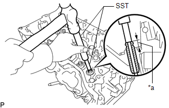
(g) Using SST, tap in new intake valve guide bushes to the specified protrusion height. Text in Illustration
SST: 09201-10000 09201-01050 SST: 09950-70010 09951-07100 Standard protrusion height: 9.10 to 9.90 mm (0.358 to 0.390 in.) |
|
|
(h) Using a sharp 5.5 mm reamer, ream the valve guide bushings to obtain the specified clearance. Standard oil clearance: 0.025 to 0.060 mm (0.000984 to 0.00236 in.) |
|
2. REPLACE EXHAUST VALVE GUIDE BUSH
(a) Heat the cylinder head to 80 to 100°C (176 to 212°F).
(b) Place the cylinder head on wooden blocks.
|
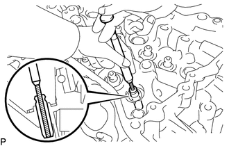
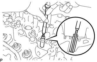
(c) Using SST and a hammer, tap out the exhaust valve guide bushes. SST: 09201-10000 09201-01050 SST: 09950-70010 09951-07100 |
|
(d) Using a caliper gauge, measure the exhaust valve guide bush bore diameter of the cylinder head.
Standard cylinder bore diameter:
10.285 to 10.306 mm (0.4049 to 0.4057 in.)
Select a New Guide Bush (STD or O/S 0.05):
|
Bush Size |
Specified Condition |
|---|---|
|
STD |
10.285 to 10.306 mm (0.4049 to 0.4057 in.) |
|
O/S 0.05 |
10.335 to 10.356 mm (0.4069 to 0.4077 in.) |
If the bush bore diameter of the cylinder head is more than 10.306 mm (0.4057 in.), machine the bush bore to the dimension of 10.335 to 10.356 mm (0.4069 to 0.4077 in.) to install an O/S 0.05 valve guide bush.
If the bush bore diameter of the cylinder head is more than 10.356 mm (0.4077 in.), replace the cylinder head.
(e) Heat the cylinder head to 80 to 100°C (176 to 212°F).
(f) Place the cylinder head on wooden blocks.
|
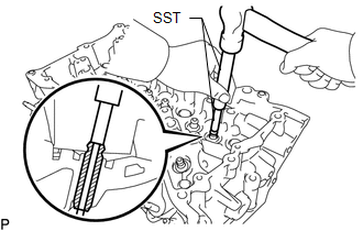
(g) Using SST, tap in new exhaust valve guide bushes to the specified protrusion height. Text in Illustration
SST: 09201-10000 09201-01050 SST: 09950-70010 09951-07100 Standard protrusion height: 9.10 to 9.90 mm (0.358 to 0.390 in.) |
|
|
(h) Using a sharp 5.5 mm reamer, ream the valve guide bushings to obtain the specified clearance. Standard oil clearance: 0.03 to 0.065 mm (0.00118 to 0.00256 in.) |
|
3. REPLACE RING PIN
NOTICE:
It is not necessary to remove the ring pin unless it is being replaced.
|
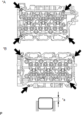
(a) Using a plastic-faced hammer, tap in new ring pins to the specified protrusion height. Text in Illustration
Standard protrusion height: 2.5 to 3.5 mm (0.0984 to 0.138 in.) |
|
4. REPLACE STRAIGHT PIN
NOTICE:
It is not necessary to remove the straight pin unless it is being replaced.
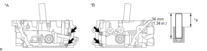
(a) Using a plastic-faced hammer, tap in new straight pins as shown in the illustration.
 Text in Illustration
|
*A |
Bank 1 |
*B |
Bank 2 |
|
*a |
Protrusion Height |
- |
- |
Standard protrusion height:
17.5 to 19.5 mm (0.689 to 0.768 in.)
 Inspection
INSPECTION
PROCEDURE
1. INSPECT CYLINDER HEAD SUB-ASSEMBLY
(a) Using a precision straightedge and feeler gauge, measure the warpage of the
contact surfaces where the cylinder head contacts the cy ...
 Reassembly
REASSEMBLY
CAUTION / NOTICE / HINT
HINT:
Perform "Inspection After Repairs" after replacing the cylinder head sub-assembly
or cylinder head LH (See page ).
PROCEDURE
1. INSTALL SPARK ...
Other materials:
Status Signal Circuit
DESCRIPTION
This circuit sends a smart key system status signal from the certification ECU
(smart key ECU assembly) to the mobile wireless charger cradle assembly. Based on
this signal, the mobile wireless charger cradle assembly suspends or resumes wireless
charging.
WIRING DIAGRAM
CAUTI ...
Inspection
INSPECTION
PROCEDURE
1. INSPECT WINDSHIELD WIPER MOTOR ASSEMBLY
(a) Check the LO operation.
Text in Illustration
*a
Component without harness connected
(Windshield Wiper Motor Assembly)
(1) Apply battery voltage to the windshield wiper motor connector and ch ...
Precaution
PRECAUTION
1. IGNITION SWITCH EXPRESSIONS
(a) The type of ignition switch used on this model differs according to the specifications
of the vehicle. The expressions listed in the table below are used in this section.
Expression
Ignition Switch (Position)
Engine ...
