Toyota Tacoma (2015-2018) Service Manual: TC and CG Terminal Circuit
DESCRIPTION
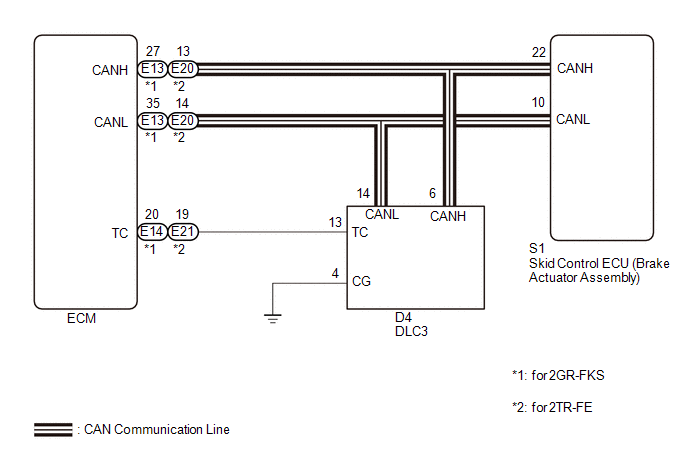
Connecting terminals TC and CG of the DLC3 causes the ECU to display the DTC by blinking the ABS warning light and slip indicator light.
WIRING DIAGRAM
CAUTION / NOTICE / HINT
NOTICE:
When replacing the skid control ECU (brake actuator assembly), perform zero point
calibration and store system information (See page
.gif) ).
).
PROCEDURE
|
1. |
CHECK CAN COMMUNICATION SYSTEM |
(a) Check if CAN communication system DTCs are output (See page
).
|
Result |
Proceed to |
|---|---|
|
DTC is not output |
A |
|
DTC is output |
B |
| B | .gif) |
CHECK CAN COMMUNICATION SYSTEM |
|
.gif)
|
2. |
INSPECT DLC3 |
|
(a) Turn the ignition switch to ON. |
|
(b) Measure the voltage according to the value(s) in the table below.
Standard Voltage:
|
Tester Connection |
Switch Condition |
Specified Condition |
|---|---|---|
|
D4-13 (TC) - D4-4 (CG) |
Ignition switch ON |
11 to 14 V |
|
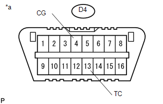
*a |
Front view of DLC3 |
| NG | |
GO TO STEP 4 |
|
|
3. |
REPLACE ECM |
|
(a) Turn the ignition switch off. |
|
(b) Replace the ECM.
- for 2GR-FKS: (See page
)
- for 2TR-FE: (See page
)
(c) Using SST, connect terminals 13 (TC) and 4 (CG) of the DLC3.
SST: 09843-18040
(d) Check that the ABS warning and slip indicator lights are blinking.
OK:
The ABS warning and slip indicator lights are blinking.
Text in Illustration|
*a |
Front view of DLC3 |
| OK | |
END |
| NG | |
REPLACE BRAKE ACTUATOR ASSEMBLY |
|
4. |
CHECK HARNESS AND CONNECTOR (TC of DLC3 - ECM) |
(a) Turn the ignition switch off.
(b) Disconnect the E13*1, E21*2 ECM connector.
- *1: for 2GR-FKS
- *2: for 2TR-FE
(c) Measure the resistance according to the value(s) in the table below.
Standard Resistance:
for 2GR-FKS:|
Tester Connection |
Condition |
Specified Condition |
|---|---|---|
|
D4-13 (TC) - E14-20 (TC) |
Always |
Below 1 Ω |
|
D4-13 (TC) or E14-20 (TC) - Body ground |
Always |
10 kΩ or higher |
|
Tester Connection |
Condition |
Specified Condition |
|---|---|---|
|
D4-13 (TC) - E21-19 (TC) |
Always |
Below 1 Ω |
|
D4-13 (TC) or E21-19 (TC) - Body ground |
Always |
10 kΩ or higher |
| NG | |
REPAIR OR REPLACE HARNESS OR CONNECTOR |
|
|
5. |
CHECK HARNESS AND CONNECTOR (CG of DLC3 - BODY GROUND) |
|
(a) Measure the resistance according to the value(s) in the table below. Standard Resistance:
|
|
| NG | |
REPAIR OR REPLACE HARNESS OR CONNECTOR |
|
|
6. |
REPLACE ECM |
|
(a) Replace the ECM.
|
|
(b) Using SST, connect terminals 13 (TC) and 4 (CG) of the DLC3.
SST: 09843-18040
(c) Check that the ABS warning and slip indicator lights are blinking.
OK:
The ABS warning and slip indicator lights are blinking.
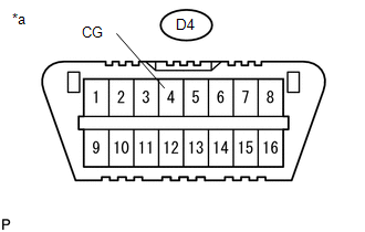
Text in Illustration|
*a |
Front view of DLC3 |
| OK | |
END |
| NG | |
REPLACE BRAKE ACTUATOR ASSEMBLY |
 Slip Indicator Light does not Come ON
DESCRIPTION
Refer to Slip Indicator Light Remains ON (See page
).
WIRING DIAGRAM
Refer to Slip Indicator Light Remains ON (See page
).
CAUTION / NOTICE / HINT
NOTICE:
When replacing the skid ...
 VSC Buzzer Circuit
DESCRIPTION
The skid control ECU (brake actuator assembly) is connected to the combination
meter via CAN communication.
The combination meter has a built-in VSC warning buzzer:
Sounds inte ...
Other materials:
Disassembly
DISASSEMBLY
PROCEDURE
1. REMOVE REAR AXLE SHAFT SNAP RING
(a) Using a snap ring expander, remove the snap ring.
2. REMOVE REAR AXLE SHAFT
(a) Using SST and press, remove the rear axle shaft.
SST: 09521-25011
SST: 09521-25021
3. REMOVE REAR AXLE BEARING RETAINER INNER
(a) Remove the rear ...
Cruise Control Switch Circuit
DESCRIPTION
The cruise control main switch is used to turn the dynamic radar cruise control
system on and off, as well as operate 7 functions: SET, - (COAST), TAP-DOWN, RES
(RESUME), + (ACCEL), TAP-UP and CANCEL.
The SET, TAP-DOWN and - (COAST) functions, and the RES (RESUME), TAP-UP and +
( ...
Input Speed Sensor Circuit No Signal (P0717,P07BF,P07C0)
DESCRIPTION
This sensor detects the rotation speed of the turbine which shows the input turbine
speed of the transmission. By comparing the input turbine speed signal (NT) with
the output shaft speed sensor signal (SP2), the ECM detects the shift timing of
the gears and appropriately controls ...
