Toyota Tacoma (2015-2018) Service Manual: Rear Power Outlet Switch
Components
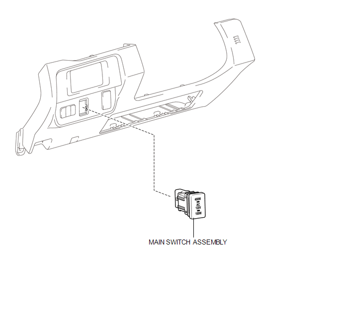
COMPONENTS
ILLUSTRATION
Inspection
INSPECTION
PROCEDURE
1. INSPECT MAIN SWITCH ASSEMBLY
(a) Check the main switch assembly.
|
(1) Measure the resistance according to the value(s) in the table below. Text in Illustration
Standard Resistance:
|
|
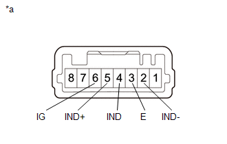
(b) Check the switch indicator.
(1) Apply battery voltage to the main switch assembly and check that the switch indicator illuminates.
OK:
|
Measurement Condition |
Switch Condition |
Specified Condition |
|---|---|---|
|
Battery positive (+) → 5 (IND+) Battery positive (-) → 2 (IND-) |
Always |
Illuminates |
OK:
|
Measurement Condition |
Switch Condition |
Specified Condition |
|---|---|---|
|
Battery positive (+) → 6 (IG) Battery positive (-) → 4 (IND) |
Always |
Illuminates |
- If the specified condition is not met, replace the main switch assembly.
Removal
REMOVAL
PROCEDURE
1. REMOVE INSTRUMENT PANEL LOWER FINISH PANEL SUB-ASSEMBLY RH
(See page .gif) )
)
2. REMOVE MAIN SWITCH ASSEMBLY
|
(a) Disengage the 2 claws to remove the main switch assembly. |
|
Installation
INSTALLATION
PROCEDURE
1. INSTALL MAIN SWITCH ASSEMBLY
(a) Engage the 2 claws to install the main switch assembly.
2. INSTALL INSTRUMENT PANEL LOWER FINISH PANEL SUB-ASSEMBLY RH
(See page .gif) )
)
 Rear Power Outlet Socket
Components
COMPONENTS
ILLUSTRATION
ILLUSTRATION
Installation
INSTALLATION
PROCEDURE
1. INSTALL POWER OUTLET SOCKET ASSEMBLY
(a) Install the clamp.
(b) Connect the connector.
...
 Voltage Inverter
Components
COMPONENTS
ILLUSTRATION
Inspection
INSPECTION
PROCEDURE
1. INSPECT VOLTAGE INVERTER ASSEMBLY
(a) Check the voltage inverter assembly.
(1) Measure the voltage according to the ...
Other materials:
Transfer Shift Motor Control Circuit High (P17AA)
DESCRIPTION
This DTC is output when a short to B+ in the transfer shift motor and A.D.D.
shift motor drive circuit is detected.
DTC No.
Detection Item
DTC Detection Condition
Trouble Area
P17AA
Transfer Shift Motor Control C ...
Lost Communication with ECM (C1437)
DESCRIPTION
The skid control ECU (brake actuator assembly) receives signals from the ECM
via the CAN communication system.
DTC No.
Detection Item
DTC Detection Condition
Trouble Area
C1437
Lost Communication with ECM
...
Removal
REMOVAL
PROCEDURE
1. REMOVE FRONT FENDER SEAL LH
(a) Remove the 5 clips and front fender seal LH.
2. REMOVE FRONT FENDER SEAL RH
HINT:
Use the same procedure as for the LH side.
3. REMOVE FRONT EXHAUST PIPE ASSEMBLY
(a) Disengag ...
