Toyota Tacoma (2015-2018) Service Manual: Parts Location
PARTS LOCATION
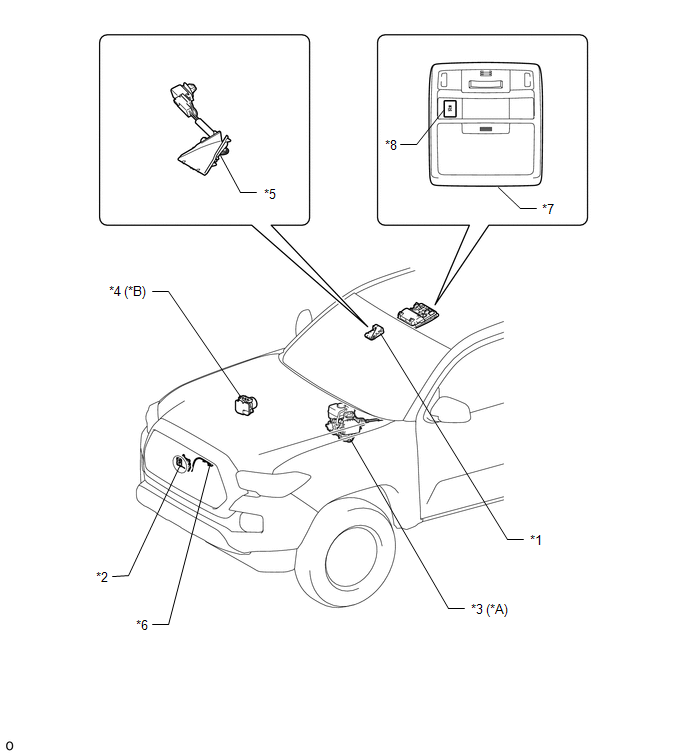
ILLUSTRATION
|
*A |
for Hydraulic Brake Booster |
*B |
for Vacuum Brake Booster |
|
*1 |
FORWARD RECOGNITION CAMERA |
*2 |
MILLIMETER WAVE RADAR SENSOR ASSEMBLY |
|
*3 |
HYDRAULIC BRAKE BOOSTER - SKID CONTROL ECU |
*4 |
BRAKE ACTUATOR ASSEMBLY - SKID CONTROL ECU |
|
*5 |
FORWARD RECOGNITION HOOD |
*6 |
MILLIMETER WAVE RADAR WIRE |
|
*7 |
ROOF CONSOLE BOX ASSEMBLY |
*8 |
VSC OFF SWITCH |
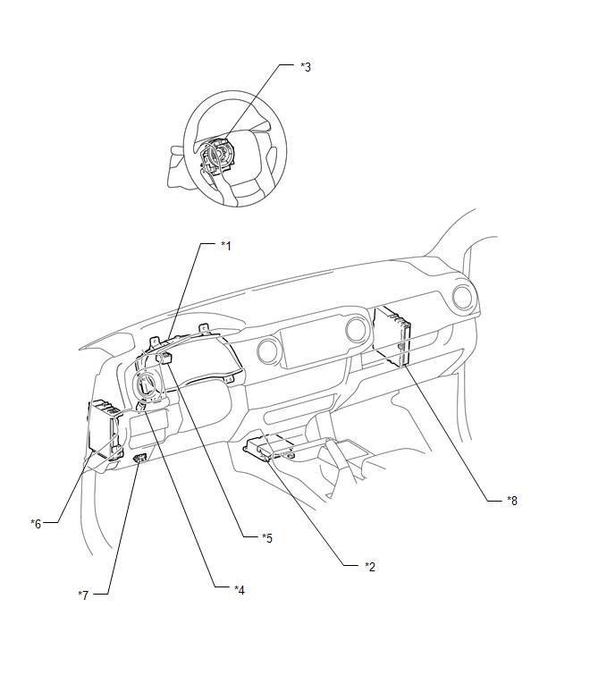
ILLUSTRATION
|
*1 |
COMBINATION METER ASSEMBLY - PCS WARNING LIGHT |
*2 |
AIRBAG SENSOR ASSEMBLY - YAW RATE SENSOR |
|
*3 |
STEERING ANGLE SENSOR (SPIRAL CABLE WITH SENSOR SUB-ASSEMBLY) |
*4 |
STOP LIGHT SWITCH ASSEMBLY |
|
*5 |
SKID CONTROL BUZZER |
*6 |
DRIVER SIDE JUNCTION BLOCK - ECU-IG NO. 2 - IG1 NO. 2 |
|
*7 |
DLC3 |
*8 |
ECM |
 Precaution
PRECAUTION
PRECAUTION FOR DISCONNECTING CABLE FROM NEGATIVE BATTERY TERMINAL
NOTICE:
When disconnecting the cable from the negative (-) battery terminal,
initialize the following system ...
 System Description
SYSTEM DESCRIPTION
PRE-COLLISION SYSTEM DESCRIPTION
(a) The pre-collision system uses the pre-collision warning control, pre-collision
brake assist control and pre-collision braking control to hel ...
Other materials:
Open in Stop Light Switch Circuit (C1425)
DESCRIPTION
The skid control ECU (brake actuator assembly) detects the brake operating conditions
through a signal transmitted by the stop light switch.
The skid control ECU incorporates a circuit to detect an open circuit. This DTC
is output when an open circuit is detected in the stop light ...
Coolant
Replacement
REPLACEMENT
PROCEDURE
1. REMOVE NO. 2 ENGINE UNDER COVER SUB-ASSEMBLY (w/ Off Road Package)
2. REMOVE NO. 1 ENGINE UNDER COVER SUB-ASSEMBLY
3. DRAIN ENGINE COOLANT
CAUTION:
Do not remove the radiator cap sub-assembly, cylinder block drain cock
plug or radiator drain ...
Open in Bus 5 Main Bus Line
DESCRIPTION
There may be an open circuit in one of the CAN main bus lines when the resistance
between terminals 15 (CA5H) and 16 (CA5L) of the central gateway ECU (network gateway
ECU) is 70 ╬® or higher.
Detection Item
Trouble Area
Resistance between ter ...
