Toyota Tacoma (2015-2018) Service Manual: Transmitter ID not Received in Main Mode (C2126/26)
DESCRIPTION
After all transmitter IDs are registered, DTC C2126/26 is stored in the tire pressure warning ECU and receiver and the tire pressure warning light blinks for 1 minute and then illuminates.
When the tire pressure warning ECU and receiver successfully receives radio waves from all the transmitters whose IDs are stored in the ECU, DTC C2126/26 is cleared and the tire pressure warning light goes off.
|
DTC No. |
Detection Item |
DTC Detection Condition |
Trouble Area |
Note |
|---|---|---|---|---|
|
C2126/26 |
Transmitter ID not Received in Main Mode |
After transmitter ID registration is completed, ECU does not receive radio waves from transmitters whose IDs are stored in ECU. |
|
- |
HINT:
The purpose of this DTC is to help prevent delivering a vehicle that has incorrectly registered transmitter IDs. After all IDs are registered, DTC C2126/26 is stored and the tire pressure warning light blinks for 1 minute and then illuminates. If the tire pressure warning light does not go off after a little while, the transmitter IDs may be incorrectly registered.
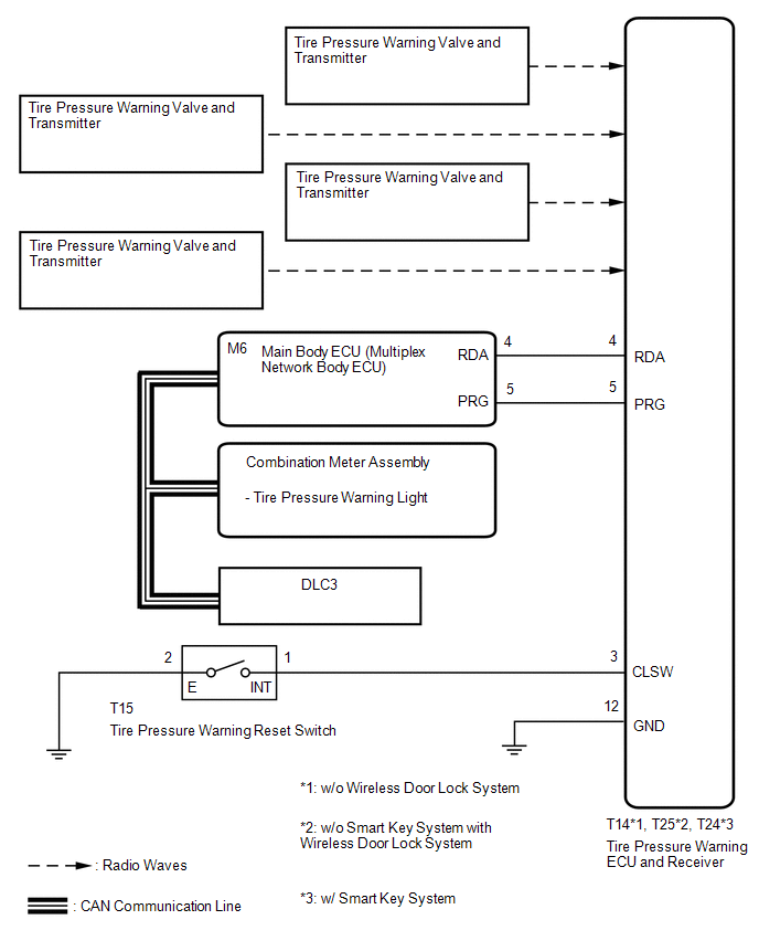
WIRING DIAGRAM
CAUTION / NOTICE / HINT
NOTICE:
- When replacing the tire pressure warning ECU and receiver, read the transmitter IDs stored in the old ECU using the Techstream and write them down before removal.
- It is necessary to perform initialization (See page
.gif) ) after registration (See page
) of the transmitter IDs into the tire
pressure warning ECU and receiver if the ECU and/or one of the valve and
transmitters has been replaced.
) after registration (See page
) of the transmitter IDs into the tire
pressure warning ECU and receiver if the ECU and/or one of the valve and
transmitters has been replaced.
PROCEDURE
|
1. |
IDENTIFY TRANSMITTER NOT RECEIVED |
(a) Set the tire pressure to the specified value (See page
).
(b) Turn the ignition switch off.
(c) Connect the Techstream to the DLC3.
(d) Turn the ignition switch to ON.
(e) Turn the Techstream on.
(f) Enter the following menus: Chassis / Tire Pressure Monitor / Data List.
(g) Display the "ID Tire Inflation Pressure" value for each wheel using the Techstream.
(h) Rapidly reduce the tire pressure for each wheel at least 40 kPa (0.4 kg/cm2, 5.8 psi) within 30 seconds. If the "ID Tire Inflation Pressure" value displayed on the Techstream does not change, the tire pressure warning valve and transmitter corresponding to the unchanged "ID Tire Inflation Pressure" value was the cause of the output DTC.
HINT:
- Identify the malfunctioning tire pressure warning valve and transmitter by repeatedly decreasing the tire pressure for each tire.
- Record which "ID Tire Inflation Pressure" value corresponds to each tire.
|
Tester Display |
Measurement Item/Range |
Normal Condition |
Diagnostic Note |
|---|---|---|---|
|
ID 1 Tire Inflation Pressure |
ID1 tire inflation pressure/ min.: Absolute pressure (abs) / 0 kPa (0 kgf/cm2, 0 psi), Relative pressure (Gauge) / 0 kPa (0 kgf/cm2, 0 psi) max.: Absolute pressure (abs) / 480 kPa (4.9 kgf/cm2, 70 psi), Relative pressure (Gauge) / 380 kPa (3.9 kgf/ cm2, 55 psi) |
Actual tire inflation pressure |
If N/A is displayed, data has not been received.*1 |
|
ID 2 Tire Inflation Pressure |
ID2 tire inflation pressure/ min.: Absolute pressure (abs) / 0 kPa (0 kgf/cm2, 0 psi), Relative pressure (Gauge) / 0 kPa (0 kgf/cm2, 0 psi) max.: Absolute pressure (abs) / 480 kPa (4.9 kgf/cm2, 70 psi), Relative pressure (Gauge) / 380 kPa (3.9 kgf/ cm2, 55 psi) |
Actual tire inflation pressure |
If N/A is displayed, data has not been received.*1 |
|
ID 3 Tire Inflation Pressure |
ID3 tire inflation pressure/ min.: Absolute pressure (abs) / 0 kPa (0 kgf/cm2, 0 psi), Relative pressure (Gauge) / 0 kPa (0 kgf/cm2, 0 psi) max.: Absolute pressure (abs) / 480 kPa (4.9 kgf/cm2, 70 psi), Relative pressure (Gauge) / 380 kPa (3.9 kgf/ cm2, 55 psi) |
Actual tire inflation pressure |
If N/A is displayed, data has not been received.*1 |
|
ID 4 Tire Inflation Pressure |
ID4 tire inflation pressure/ min.: Absolute pressure (abs) / 0 kPa (0 kgf/cm2, 0 psi), Relative pressure (Gauge) / 0 kPa (0 kgf/cm2, 0 psi) max.: Absolute pressure (abs) / 480 kPa (4.9 kgf/cm2, 70 psi), Relative pressure (Gauge) / 380 kPa (3.9 kgf/ cm2, 55 psi) |
Actual tire inflation pressure |
If N/A is displayed, data has not been received.*1 |
HINT:
*1: It may take a few minutes until the values are displayed.
(i) Check the Data List.
NOTICE:
- It may take a few minutes until the values are displayed.
- When an "ID Tire Inflation Pressure" value has not changed, reset the tire pressure to the appropriate specified value and rotate the tire 90 to 270 degrees. Then rapidly release the tire pressure and recheck the value.
- Record the transmitter IDs and positions of transmitters that are normal.
(j) After confirming that the "ID Tire Inflation Pressure" value for one tire has changed, repeat this procedure one by one. Identify the transmitter that corresponds to the DTC.
Result|
Result |
Proceed to |
|---|---|
|
One or more transmitter is abnormal. |
A |
|
All transmitters are normal. |
B |
| B | .gif) |
END |
|
.gif)
|
2. |
CHECK TRANSMITTER ID |
(a) Turn the ignition switch off.
(b) Connect the Techstream to the DLC3.
(c) Turn the ignition switch to ON.
(d) Turn the Techstream on.
(e) Enter the following menus: Chassis / Tire Pressure Monitor / Data List.
(f) Check the values by referring to the table below.
Tire Pressure Monitor|
Tester Display |
Measurement Item/Range |
Normal Condition |
Diagnostic Note |
|---|---|---|---|
|
Registered ID 1 Code |
Registered ID1 code/ min.: 0 max.: FFFFFFF*1 |
ID No. registered for transmitter ID1 displayed |
- |
|
Registered ID 2 Code |
Registered ID2 code/ min.: 0 max.: FFFFFFF*1 |
ID No. registered for transmitter ID2 displayed |
- |
|
Registered ID 3 Code |
Registered ID3 code/ min.: 0 max.: FFFFFFF*1 |
ID No. registered for transmitter ID3 displayed |
- |
|
Registered ID 4 Code |
Registered ID4 code/ min.: 0 max.: FFFFFFF*1 |
ID No. registered for transmitter ID4 displayed |
- |
HINT:
*1: Displayed only when the ID No. is not registered.
(g) Check the ID number on the identified transmitter by removing it from the tire and wheel.
.png) Text in Illustration
Text in Illustration
|
*1 |
Tire Pressure Warning Valve and Transmitter |
- |
- |
|
*a |
Transmitter ID (7-digit Number) |
- |
- |
(h) Confirm that the ID number on the transmitter and recorded transmitter ID match.
Result|
Result |
Proceed to |
|---|---|
|
Match |
A |
|
Do not match |
B |
| B | |
GO TO STEP 4 |
|
|
3. |
REPLACE TIRE PRESSURE WARNING VALVE AND TRANSMITTER |
(a) Replace the tire pressure warning valve and transmitter (See page
).
|
|
4. |
REGISTRATION OF TRANSMITTER ID |
(a) Perform registration (See page ).
|
|
5. |
PERFORM INITIALIZATION |
(a) Perform initialization (See page ).
|
|
6. |
CONFIRM TIRE INFLATION PRESSURE (DATA LIST) |
(a) Turn the ignition switch off.
(b) Connect the Techstream to the DLC3.
(c) Turn the ignition switch to ON.
(d) Turn the Techstream on.
(e) Enter the following menus: Chassis / Tire Pressure Monitor / Data List.
(f) Check the values by referring to the table below.
Tire Pressure Monitor|
Tester Display |
Measurement Item/Range |
Normal Condition |
Diagnostic Note |
|---|---|---|---|
|
ID 1 Tire Inflation Pressure |
ID1 tire inflation pressure/ min.: Absolute pressure (abs) / 0 kPa (0 kgf/cm2, 0 psi), Relative pressure (Gauge) / 0 kPa (0 kgf/cm2, 0 psi) max.: Absolute pressure (abs) / 480 kPa (4.9 kgf/cm2, 70 psi), Relative pressure (Gauge) / 380 kPa (3.9 kgf/ cm2, 55 psi) |
Actual tire inflation pressure |
If N/A is displayed, data has not been received.*1 |
|
ID 2 Tire Inflation Pressure |
ID2 tire inflation pressure/ min.: Absolute pressure (abs) / 0 kPa (0 kgf/cm2, 0 psi), Relative pressure (Gauge) / 0 kPa (0 kgf/cm2, 0 psi) max.: Absolute pressure (abs) / 480 kPa (4.9 kgf/cm2, 70 psi), Relative pressure (Gauge) / 380 kPa (3.9 kgf/ cm2, 55 psi) |
Actual tire inflation pressure |
If N/A is displayed, data has not been received.*1 |
|
ID 3 Tire Inflation Pressure |
ID3 tire inflation pressure/ min.: Absolute pressure (abs) / 0 kPa (0 kgf/cm2, 0 psi), Relative pressure (Gauge) / 0 kPa (0 kgf/cm2, 0 psi) max.: Absolute pressure (abs) / 480 kPa (4.9 kgf/cm2, 70 psi), Relative pressure (Gauge) / 380 kPa (3.9 kgf/ cm2, 55 psi) |
Actual tire inflation pressure |
If N/A is displayed, data has not been received.*1 |
|
ID 4 Tire Inflation Pressure |
ID4 tire inflation pressure/ min.: Absolute pressure (abs) / 0 kPa (0 kgf/cm2, 0 psi), Relative pressure (Gauge) / 0 kPa (0 kgf/cm2, 0 psi) max.: Absolute pressure (abs) / 480 kPa (4.9 kgf/cm2, 70 psi), Relative pressure (Gauge) / 380 kPa (3.9 kgf/ cm2, 55 psi) |
Actual tire inflation pressure |
If N/A is displayed, data has not been received.*1 |
HINT:
- *1: It may take a few minutes until the values are displayed.
- When an "ID Tire Inflation Pressure" value has not changed, reset the tire pressure to the appropriate specified value and rotate the tire 90 to 270 degrees. Then rapidly release the tire pressure and recheck the value.
|
Result |
Proceed to |
|---|---|
|
Tire pressure values are not displayed. |
A |
|
All tire pressure readings are equal to specified values. |
B |
| A | |
REPLACE TIRE PRESSURE WARNING ECU AND RECEIVER |
| B | |
END |
 Dtc Check / Clear
DTC CHECK / CLEAR
1. CHECK DTC (for TIRE PRESSURE WARNING ECU AND RECEIVER) (USING TECHSTREAM)
(a) Turn the ignition switch off.
(b) Connect the Techstream to the DLC3.
(c) Turn the ignition switc ...
 Transmitter ID1 Error (C2141/41-C2144/44)
DESCRIPTION
The tire pressure warning valve and transmitters that are installed in the tire
and wheel assemblies measure the tire pressure of each wheel. The measured values
are transmitted to th ...
Other materials:
Problem Symptoms Table
PROBLEM SYMPTOMS TABLE
HINT:
Use the table below to help determine the cause of problem symptoms.
If multiple suspected areas are listed, the potential causes of the symptoms
are listed in order of probability in the "Suspected Area" column of the
table. Check each sy ...
4WD ECU Malfunction (P163B)
DESCRIPTION
This DTC is output when a malfunction is detected in the 4 wheel drive control
ECU internal circuit.
DTC No.
Detection Item
DTC Detection Condition
Trouble Area
P163B
4WD ECU Malfunction
Dia ...
Starting System
Parts Location
PARTS LOCATION
ILLUSTRATION
ILLUSTRATION
Precaution
PRECAUTION
1. IGNITION SWITCH EXPRESSIONS
(a) The type of ignition switch used on this model differs depending on the specifications
of the vehicle. The expressions listed in the table below are used in this section. ...
