Toyota Tacoma (2015-2018) Service Manual: Steering Pad Switch
Components
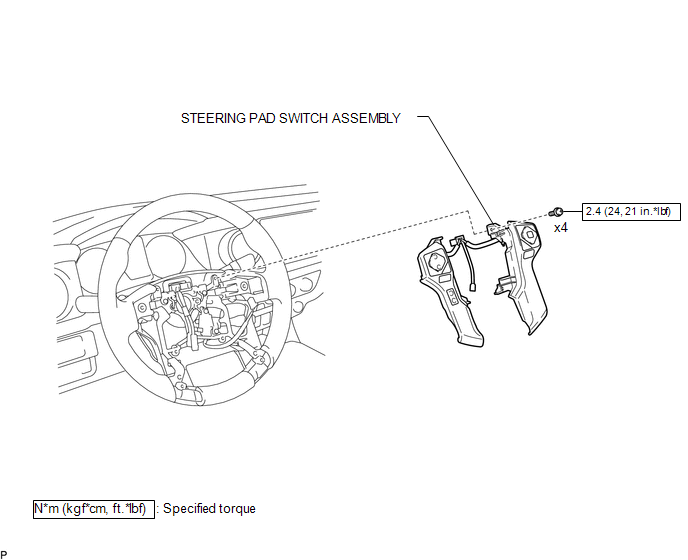
COMPONENTS
ILLUSTRATION
Removal
REMOVAL
PROCEDURE
1. REMOVE STEERING PAD
(See page .gif) )
)
2. REMOVE STEERING PAD SWITCH ASSEMBLY
|
(a) Disconnect the 2 connectors. |
|
.png)
(b) Disengage the 2 clamps.
(c) Remove the 4 screws.
|
(d) Disengage the 6 guides and 2 claws to remove the steering pad switch assembly. NOTICE: Disengage the 2 guides on the upper part of the steering pad switch assembly first. |
|
.png)
Inspection
INSPECTION
PROCEDURE
1. INSPECT STEERING PAD SWITCH ASSEMBLY
(See page .gif) )
)
Installation
INSTALLATION
PROCEDURE
1. INSTALL STEERING PAD SWITCH ASSEMBLY
(a) Engage the 6 guides and 2 claws to install the steering pad switch assembly.
(b) Install the 4 screws.
Torque:
2.4 N·m {24 kgf·cm, 21 in·lbf}
(c) Engage the 2 clamps.
(d) Connect the 2 connectors.
2. INSTALL STEERING PAD
(See page .gif) )
)
 Speed Signal Circuit
DESCRIPTION
The combination meter assembly receives the vehicle speed signal from this circuit.
The wheel speed sensors produce an output that varies according to the vehicle speed.
The wheel spe ...
 Mirror
...
Other materials:
Sound Signal Circuit between Radio Receiver and Stereo Component Amplifier
DESCRIPTION
The navigation receiver assembly sends a sound signal to the stereo component
amplifier assembly via this circuit.
The sound signal that has been sent is amplified by the stereo component amplifier
assembly, and then is sent to the speakers.
If there is an open or short in the cir ...
Camshaft
Components
COMPONENTS
ILLUSTRATION
ILLUSTRATION
ILLUSTRATION
ILLUSTRATION
ILLUSTRATION
*1
FUEL PUMP ASSEMBLY
*2
FUEL PUMP LIFTER ASSEMBLY
*3
FUEL PUMP LIFTER GUIDE
*4
FUEL PUMP SPACER GAS ...
Removal
REMOVAL
PROCEDURE
1. PRECAUTION
NOTICE:
After turning the ignition switch off, waiting time may be required before disconnecting
the cable from the negative (-) battery terminal.
Therefore, make sure to read the disconnecting the cable from the negative (-)
battery terminal notices before p ...
