Toyota Tacoma (2015-2018) Service Manual: Inspection
INSPECTION
PROCEDURE
1. INSPECT REAR NO. 2 POWER WINDOW REGULATOR SWITCH ASSEMBLY
|
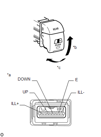
*a |
Component without harness connected (Rear No. 2 Power Window Regulator Switch Assembly) |
|
*b |
Pull (Close) |
|
*c |
Push (Open) |
(a) Check the resistance.
(1) Measure the resistance according to the value(s) in the table below.
Standard Resistance:
|
Tester Connection |
Switch Condition |
Specified Condition |
|
|---|---|---|---|
|
6 (UP) - 2 (E) |
Pull (Close) |
Pulled |
Below 1 Ω |
|
Not pulled |
10 kΩ or higher |
||
|
4 (DOWN) - 2 (E) |
Push (Open) |
Pushed |
Below 1 Ω |
|
Not pushed |
10 kΩ or higher |
||
If the result is not as specified, replace the rear No. 2 power window regulator switch assembly.
(b) Check that the LED illuminates.
(1) Apply battery voltage to the rear No. 2 power window regulator switch assembly.
OK:
|
Measurement Condition |
Specified Condition |
|---|---|
|
Battery positive (+) → 8 (ILL+) Battery negative (-) → 1 (ILL-) |
LED illuminates |
If the result is not as specified, replace the rear No. 2 power window regulator switch assembly.
 Components
COMPONENTS
ILLUSTRATION
*1
INSTRUMENT LOWER PANEL ASSEMBLY
*2
INSTRUMENT PANEL LOWER CENTER FINISH PANEL
*3
NO. 2 INSTRUMENT ...
 Removal
REMOVAL
PROCEDURE
1. REMOVE AIR CONDITIONING CONTROL ASSEMBLY (for Automatic Air Conditioning System)
Click here
2. REMOVE AIR CONDITIONING CONTROL ASSEMBLY (for Manual Air Conditioning System)
...
Other materials:
Removal
REMOVAL
CAUTION / NOTICE / HINT
HINT:
If the bumper is damaged, there is a possibility that the installation area of
the blind spot monitor sensor may be deformed and the blind spot monitor system
may not operate correctly, so visually inspect the blind spot monitor sensor installation
area ...
Installation
INSTALLATION
PROCEDURE
1. INSTALL OIL COOLER ASSEMBLY (w/ Air Cooled Transmission Oil Cooler)
(a) Install the 2 oil cooler brackets to the oil cooler assembly with the 2 bolts.
Torque:
5.5 N·m {56 kgf·cm, 49 in·lbf}
(b) Install the oil cooler assembly to the vehicle body with th ...
Problem Symptoms Table
PROBLEM SYMPTOMS TABLE
HINT:
Use the table below to help determine the cause of problem symptoms. If multiple
suspected areas are listed, the potential causes of the symptoms are listed in order
of probability in the "Suspected Area" column of the table. Check each symptom by
check ...
