Toyota Tacoma (2015-2018) Service Manual: Vanity Light
Components
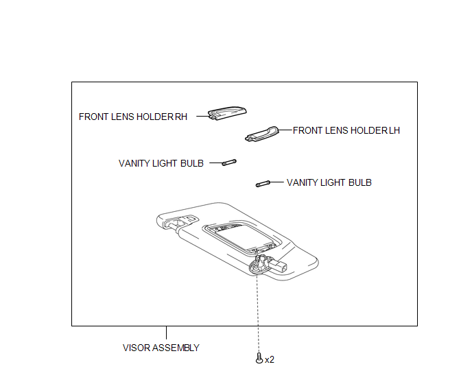
COMPONENTS
ILLUSTRATION
Removal
REMOVAL
CAUTION / NOTICE / HINT
HINT:
- Use the same procedures for the LH and RH side.
- The procedures listed below are for the LH side.
PROCEDURE
1. REMOVE VISOR ASSEMBLY
|
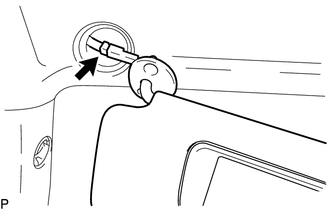
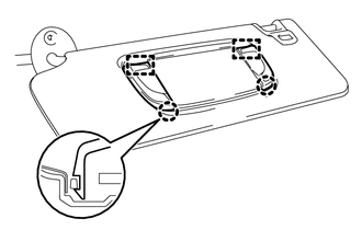
(a) Disengage the guide to separate the visor shaft. |
|
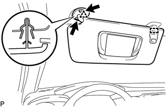
(b) Remove the 2 screws.
(c) Disengage the clip to separate the visor assembly.
|
(d) Disconnect the connector to remove the visor assembly. |
|
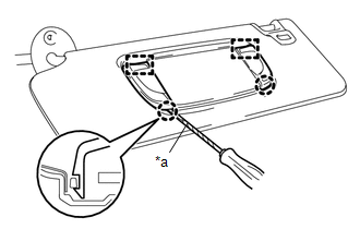
2. REMOVE VANITY LIGHT BULB
|
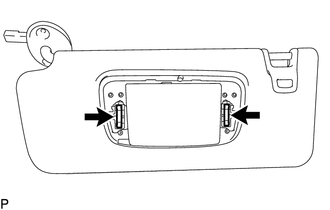
(a) Using a screwdriver with its tip wrapped in protective tape, disengage the 2 claws and 2 guides to remove the front lens holder LH and front lens holder RH. Text in Illustration
|
|
|
(b) Remove the 2 vanity light bulbs from the visor assembly. |
|
Installation
INSTALLATION
CAUTION / NOTICE / HINT
HINT:
- Use the same procedures for the LH and RH side.
- The procedures listed below are for the LH side.
PROCEDURE
1. INSTALL VANITY LIGHT BULB
(a) Install the 2 vanity light bulbs to the visor assembly.
|
(b) Engage the 2 guides and 2 claws to install the front lens holder LH and front lens holder RH. |
|
2. INSTALL VISOR ASSEMBLY
(a) Connect the connector.
(b) Engage the clip to install the visor assembly.
(c) Install the 2 screws.
(d) Engage the guide to install the visor shaft.
 Trailer Socket
Components
COMPONENTS
ILLUSTRATION
Removal
REMOVAL
PROCEDURE
1. REMOVE TRAILER SOCKET
(a) Disconnect the connector.
(b) Di ...

Other materials:
Radio Antenna Cord
Components
COMPONENTS
ILLUSTRATION
Removal
REMOVAL
PROCEDURE
1. REMOVE INSTRUMENT PANEL SUB-ASSEMBLY
(See page )
2. REMOVE ANTENNA CORD SUB-ASSEMBLY
(a) Disengage the 4 clamps to remove the antenna cord sub-assembly.
Installation
INSTALLATION
PROCEDURE
1. INSTALL ANTENNA COR ...
Terminals Of Ecm
TERMINALS OF ECM
HINT:
The standard normal voltage between each pair of ECM terminals is shown in the
table below. The appropriate conditions for checking each pair of terminals are
also indicated. The result of checks should be compared with the standard normal
voltage for that pair of te ...
Diagnosis System
DIAGNOSIS SYSTEM
1. DESCRIPTION
(a) To check DTCs, connect the Techstream to the Data Link Connector 3 (DLC3)
of the vehicle. The Techstream displays DTCs and freeze frame data. The DTCs and
freeze frame data can be cleared with the Techstream (See page
).
2. NORMAL MODE AND CHECK MODE
(a) ...
