Toyota Tacoma (2015-2018) Service Manual: Test Mode Procedure
TEST MODE PROCEDURE
1. TEST MODE (SIGNAL CHECK MODE) PROCEDURE
HINT:
- When entering test mode (signal check mode), the tire pressure warning
ECU and receiver stores all the test mode (signal check mode) DTCs first.
After the tire pressure warning ECU and receiver completes the signal check for each inspection item, the DTCs for systems that are determined to be normal will be cleared. The DTCs for other inspection items may not be cleared when only a certain signal is inspected.
- When test mode (signal check mode) returns to normal mode, all the test mode (signal check mode) DTCs will be cleared.
- Operation of the tire pressure warning reset switch can be checked in test mode (signal check mode).
- During test mode (signal check mode), the system will not be initialized by pushing the tire pressure warning reset switch. The circuit of the tire pressure warning reset switch can be inspected during this mode.
(a) Turn the ignition switch off.
(b) Connect the Techstream to the DLC3.
(c) Turn the ignition switch to ON and the Techstream on.
(d) Enter the following menus: Chassis / Tire Pressure Monitor / Utility / Signal Check.
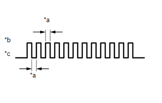 Text in Illustration
|
*a |
0.125 sec. |
|
*b |
ON |
|
*c |
OFF |
HINT:
Every time the test mode (signal check mode) DTC clear conditions are satisfied, the tire pressure warning light illuminates for 1 second. Following this, the tire pressure warning light blinks at 0.125 second intervals.
(e) Press the tire pressure warning reset switch (DTC C2198/98).
(f) Wait for 1.5 minutes with the vehicle stopped, or drive the vehicle at a speed of 50 km/h (31 mph) or more for 1 minute (DTCs C2181/81 to C2184/84).
HINT:
The tire pressure warning valve and transmitters send signals to the tire pressure warning ECU and receiver once every 1.5 minutes while the vehicle is stopped and once every minute while driving.
(g) Check that the tire pressure warning system test mode (signal check mode) DTCs are cleared.
|
Test Mode (Signal Check Mode) DTC |
Test Signal |
Test Mode (Signal Check Mode) DTC Clear Condition |
|---|---|---|
|
C2181/81 to C2184/84 |
Transmitter Data |
Data is received from the relevant transmitter which has a registered ID in the tire pressure warning ECU and receiver. |
|
C2198/98 |
Tire Pressure Warning Reset Switch Signal |
A signal is received indicating that the tire pressure warning reset switch is pressed. |
(h) Result
HINT:
After the signal check is completed, check for test mode (signal check mode) DTCs to confirm the system status.
|
Condition |
Procedure |
|---|---|
|
Test mode (signal check mode) DTCs are output |
Repair the faulty part and enter Signal Check again |
|
Test mode (signal check mode) DTCs are cleared |
No problem |
(i) End of test mode (signal check mode)
(1) After completing test mode (signal check mode), turn the ignition switch off and disconnect the Techstream.
(j) Test mode (signal check mode) DTCs
(1) If a trouble code is displayed during the test mode (signal check mode) DTC check, check the diagnosis procedure listed for that code. For details of each code, refer to Link below.
|
DTC No. |
Detection Item |
Trouble Area |
Link |
|---|---|---|---|
|
C2181/81 |
Transmitter ID1 not received |
|
|
|
C2182/82 |
Transmitter ID2 not received |
|
|
|
C2183/83 |
Transmitter ID3 not received |
|
|
|
C2184/84 |
Transmitter ID4 not received |
|
|
|
C2198/98 |
Initialization switch error |
|
|
.gif)
 Terminals Of Ecu
TERMINALS OF ECU
1. CHECK TIRE PRESSURE WARNING ECU AND RECEIVER
(a) Disconnect the T14 tire pressure warning ECU and receiver connector and measure
the voltage and resistance on the wire harness ...
 Data List / Active Test
DATA LIST / ACTIVE TEST
1. READ DATA LIST
HINT:
Using the Techstream to read the Data List allows the values or states of switches,
sensors, actuators and other items to be read without removing ...
Other materials:
Terminals Of Ecu
TERMINALS OF ECU
1. CHECK TIRE PRESSURE WARNING ECU AND RECEIVER
(a) Disconnect the T14 tire pressure warning ECU and receiver connector and measure
the voltage and resistance on the wire harness side.
Text in Illustration
*A
w/o Wireless Door Lock System
...
Terminals Of Ecu
TERMINALS OF ECU
1. REAR TELEVISION CAMERA ASSEMBLY
(a) Disconnect the T22 television camera assembly connector.
(b) Measure the voltage and resistance according to the value(s) in the table
below.
Terminal No. (Symbol)
Wiring Color
Terminal Description
...
Dtc Check / Clear
DTC CHECK / CLEAR
1. CHECK DTC (for TIRE PRESSURE WARNING ECU AND RECEIVER) (USING TECHSTREAM)
(a) Turn the ignition switch off.
(b) Connect the Techstream to the DLC3.
(c) Turn the ignition switch to ON.
(d) Turn the Techstream on.
(e) Enter the following menus: Chassis / Tire Pressure Monito ...
