Toyota Tacoma (2015-2018) Service Manual: Dtc Check / Clear
DTC CHECK / CLEAR
1. DTC CHECK/CLEAR (When Using Techstream)
(a) Check the DTC.
(1) Turn the ignition switch off.
(2) Connect the Techstream to the DLC3.
(3) Turn the ignition switch to ON.
(4) Turn the Techstream on.
(5) Read the DTCs following the prompts on the Techstream screen. Enter the following menus: Chassis / ABS/VSC/TRAC / Trouble Codes.
(6) Check the details of the DTCs (See page .gif) ).
).
(b) Clear the DTC.
(1) Turn the ignition switch off.
(2) Connect the Techstream to the DLC3.
(3) Turn the ignition switch to ON.
(4) Turn the Techstream on.
(5) Operate the Techstream to clear the codes. Enter the following menus: Chassis / ABS/VSC/TRAC / Trouble Codes.
(6) Clear the DTCs by following the prompts on the Techstream.
HINT:
Refer to the Techstream operator's manual for further details.
2. DTC CHECK/CLEAR (When Using SST Check Wire)
(a) Check the DTC.
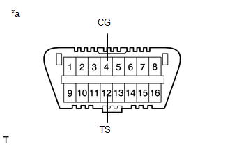
(1) Using SST, connect terminals 13 (TC) and 4 (CG) of the DLC3.
SST: 09843-18040
 Text in Illustration
|
*a |
Front view of DLC3 |
(2) Turn the ignition switch to ON.
(3) Observe the blinking pattern of the ABS warning and slip indicator lights in order to identify the DTC.
HINT:
If no code appears, inspect the TC and CG terminal circuit, and ABS warning and slip indicator lights circuits.
|
Trouble Area |
See procedure |
|---|---|
|
TC and CG terminal circuit |
|
|
ABS warning light circuit (Remains on) |
|
|
ABS warning light circuit (Does not come on) |
|
|
Slip indicator light circuit (Remains on) |
|
|
Slip indicator light circuit (Does not come on) |
|
(4) Count the number of blinks of the ABS warning and slip indicator lights.
HINT:
- When the system is operating correctly, each light will blink continuously in a pattern of 0.25 seconds on, and then 0.25 seconds off.
- When one DTC is output, each light will output the same code at 4 second intervals (for example, code 21 would be output as 2 blinks, a 1.5 second pause, and then 1 blink).
- When 2 or more DTCs are output, each light will output a different code at 2.5 second intervals, and when all codes have been output, there will be a 4 second pause and the sequence will repeat.
- When multiple codes are stored, they are output in order starting with the lowest DTC number.
(5) Check the details of the DTCs.
ABS DTC|
Warning Light Display |
Techstream Display |
|---|---|
|
11 |
C146E |
|
12 |
C146F |
|
13 |
C142B |
|
C146C |
|
|
14 |
C146D |
|
21 |
C1468 |
|
22 |
C1469 |
|
23 |
C146A |
|
24 |
C146B |
|
25 |
C1225 |
|
31 |
C1401 |
|
C1405 |
|
|
32 |
C1402 |
|
C1406 |
|
|
33 |
C1403 |
|
C1407 |
|
|
34 |
C1404 |
|
C1408 |
|
|
35 |
C1413 |
|
36 |
C1414 |
|
37 |
C1337 |
|
38 |
C1415 |
|
39 |
C1416 |
|
41 |
C120B |
|
C1241 |
|
|
C1417 |
|
|
43 |
C1232 |
|
C1243 |
|
|
44 |
C1419 |
|
C1442 |
|
|
45 |
C1245 |
|
46 |
C1421 |
|
C1422 |
|
|
C1423 |
|
|
C1424 |
|
|
C142A |
|
|
C1449 |
|
|
49 |
C1425 |
|
C1426 |
|
|
51 |
C1427 |
|
C1428 |
|
|
59 |
C1203 |
|
68 |
C1268 |
|
94 |
U0073 |
|
95 |
U0124 |
|
97 |
C1381 |
|
98 |
C1336 |
|
Warning Light Display |
Techstream Display |
|---|---|
|
31 |
C1432 |
|
C1433 |
|
|
C1434 |
|
|
34 |
C1435 |
|
C1436 |
|
|
C1443 |
|
|
36 |
C1210 |
|
51 |
C1201 |
|
63 |
U0126 |
|
64 |
C1380 |
|
65 |
C1437 |
|
U0100 |
|
|
66 |
C1290 |
|
C1439 |
|
|
C1445 |
|
|
98 |
C1440 |
(6) After completing the check, disconnect terminals TC and CG of the DLC3 to turn off the display.
HINT:
If 2 or more DTCs are detected at the same time, the DTCs will be displayed in ascending order.
(b) Clear the DTC.
(1) Using SST, connect terminals 13 (TC) and 4 (CG) of the DLC3.
SST: 09843-18040
Text in Illustration
|
*a |
Front view of DLC3 |
(2) Turn the ignition switch to ON.
(3) Clear the DTCs stored in the ECU by depressing the brake pedal 8 times or more within 5 seconds.
(4) Check that the warning light indicates a normal system code.
(5) Remove SST from the terminals of the DLC3.
HINT:
The DTCs cannot be cleared by disconnecting the battery terminal or the ECU-IG NO. 3 fuse.
3. END OF DTC CHECK/CLEAR
(a) Turn the ignition switch to ON.
(b) Check that the ABS warning and slip indicator lights go off within approximately 3 seconds after turning the ignition switch to ON.
 Terminals Of Ecu
TERMINALS OF ECU
Text in Illustration
*a
Component without harness connected
(Skid Control ECU [Brake Actuator Assembly])
-
-
Ter ...
 Fail-safe Chart
FAIL-SAFE CHART
If there is a problem with sensor signals or actuator systems, the skid
control ECU prohibits power supply to the brake actuator assembly and informs
the ECM of a VSC s ...
Other materials:
Vehicle Information Not Obtained (C1A02)
DESCRIPTION
When a new millimeter wave radar sensor assembly is installed, it receives vehicle
specification information from the main body ECU (multiplex network body ECU) and
stores the information.
DTC C1A02 is stored when the millimeter wave radar sensor assembly receives the
vehicle spe ...
Sound Signal Circuit between Radio Receiver and Stereo Component Amplifier
DESCRIPTION
The navigation receiver assembly sends a sound signal to the stereo component
amplifier assembly via this circuit.
The sound signal that has been sent is amplified by the stereo component amplifier
assembly, and then is sent to the speakers.
If there is an open or short in the cir ...
System Description
SYSTEM DESCRIPTION
1. SYSTEM FUNCTION
Function
Outline
Push-button start function
When the key is brought into the vehicle and verified, this function
changes the power source or starts the engine when the engine switch and
brake pedal are ...
