Toyota Tacoma (2015-2018) Service Manual: Terminals Of Ecu
TERMINALS OF ECU
1. CLEARANCE WARNING ECU ASSEMBLY

(a) Disconnect the C30 connector from the clearance warning ECU assembly.
(b) Measure the voltage and resistance according to the value(s) in the table below.
|
Terminal No. (Symbol) |
Wiring Color |
Terminal Description |
Condition |
Specified Condition |
|---|---|---|---|---|
|
C30-9 (CLSW) - C30-30 (E) |
Y - W-B |
Back sonar or clearance sonar switch assembly power source signal |
Ignition switch ON, back sonar or clearance sonar switch assembly on |
11 to 14 V |
|
C30-9 (CLSW) - C30-30 (E) |
Y - W-B |
Back sonar or clearance sonar switch assembly power source signal |
Ignition switch ON, back sonar or clearance sonar switch assembly off |
Below 1 V |
|
C30-1 (IG) - C30-30 (E) |
P - W-B |
IG power source signal |
Ignition switch off |
Below 1 V |
|
Ignition switch ON |
11 to 14 V |
|||
|
C30-30 (E) - Body ground |
W-B - Body ground |
Ground |
Always |
Below 1 Ω |
(c) Reconnect the C30 connector to the clearance warning ECU assembly.
(d) Measure the voltage and check for pulses according to the value(s) in the table below.
|
Terminal No. (Symbol) |
Wiring Color |
Terminal Description |
Condition |
Specified Condition |
|---|---|---|---|---|
|
C30-22 (BOR) - C30-30 (E) |
BE - W-B |
Power source for rear sensor circuit |
Ignition switch off |
Below 1 V |
|
Ignition switch ON, back sonar or clearance sonar switch assembly on |
7.2 to 8.8 V |
|||
|
C30-13 (ER) - C30-30 (E) |
R - W-B |
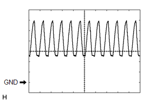
Clearance warning buzzer signal |
Buzzer sounding |
Pulse generation (See waveform 1) |
|
C30-23 (E1) - C30-30 (E) |
B - W-B |
Ground for rear clearance sonar |
Always |
Below 1 V |
|
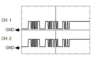
C30-24 (SOR) - C30-30 (E) |
V - W-B |
Rear sensor communication signal (Rear clearance sonar sensor) |
Ignition switch ON, back sonar or clearance sonar switch assembly on, shift lever in R |
Pulse generation (See waveform 2) |
(e) Using an oscilloscope, check waveform 1.
(1) Waveform 1 (Reference)
|
Item |
Content |
|---|---|
|
Terminal No. (Symbol) |
C30-13 (ER) - C30-30 (E) |
|
Tool Setting |
2 V/DIV., 500 ÎĽsec./DIV. |
|
Vehicle Condition |
When sonar detects obstacle (buzzer sounds) |
|
Buzzer volume |
M2 (Medium volume) |
HINT:
The amplitude of the waveform changes according to the set volume.
(f) Using an oscilloscope, check waveform 2.
(1) Waveform 2 (Reference)
|
Item |
Content |
|---|---|
|
Terminal No. (Symbol) |
C30-24 (SOR) - C30-30 (E) |
|
Tool Setting |
5 V/DIV., 1 msec./DIV. |
|
Condition |
Ignition switch ON, back sonar or clearance sonar switch assembly on, shift lever in R |
HINT:
The waveforms for CH1 and CH2 are same.
 Problem Symptoms Table
PROBLEM SYMPTOMS TABLE
HINT:
Use the table below to help determine the cause of problem symptoms.
If multiple suspected areas are listed, the potential causes of the symptoms
are lis ...
 Diagnosis System
DIAGNOSIS SYSTEM
1. DESCRIPTION
(a) When troubleshooting a vehicle with a diagnosis system, the only difference
from the usual troubleshooting procedure is connecting the Techstream to the vehicle ...
Other materials:
Satellite Radio Broadcast cannot be Selected or After Selecting Broadcast, Broadcast
cannot be Added into Memory
CAUTION / NOTICE / HINT
NOTICE:
Some satellite radio broadcasts require payment. A contract must be made between
a satellite radio company and the user. If the contract expires, it will not be
possible to listen to the broadcast.
PROCEDURE
1.
CHECK NAVIGATION RECEIVER ...
System Description
SYSTEM DESCRIPTION
1. WIRELESS CHARGER FUNCTION OUTLINE
(a) The wireless charging system enables Qi-compliant* rechargeable devices,
such as a cellular phone, to be recharged by merely placing it on the charging area
of the mobile wireless charger cradle assembly on the console panel.
HINT:
...
Disassembly
DISASSEMBLY
PROCEDURE
1. REMOVE BRAKE ACTUATOR BRACKET NO. 1
(a) Using a hexagon wrench (5 mm), remove the screw and brake actuator bracket
No. 1.
(b) Using a screwdriver, remove the fluid level warning switch connector.
2. REMOVE BRAKE M ...
