Toyota Tacoma (2015-2018) Service Manual: Door Control Receiver
Components
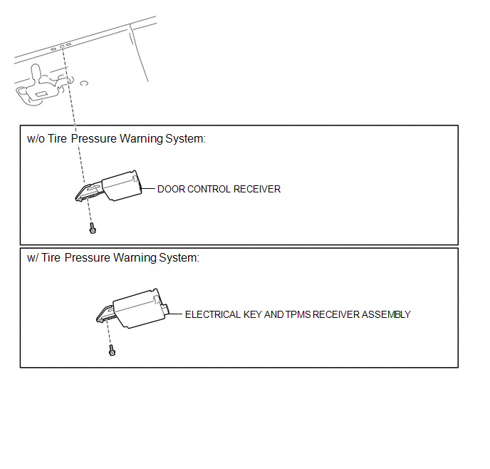
COMPONENTS
ILLUSTRATION
Removal
REMOVAL
PROCEDURE
1. REMOVE ROOF HEADLINING ASSEMBLY (for Double Cab)
(See page .gif) )
)
2. REMOVE ROOF HEADLINING ASSEMBLY (for Access Cab)
(See page )
3. REMOVE DOOR CONTROL RECEIVER (w/o Tire Pressure Warning System)
|
(a) Disconnect the connector. |
|
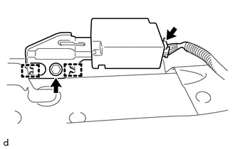
(b) Remove the bolt.
(c) Disengage the 2 hooks to remove the door control receiver.
4. REMOVE ELECTRICAL KEY AND TPMS RECEIVER ASSEMBLY (w/ Tire Pressure Warning System)
|
(a) Disconnect the connector. |
|
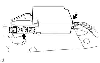
(b) Remove the bolt.
(c) Disengage the 2 hooks to remove the electrical key and TPMS receiver assembly.
Installation
INSTALLATION
PROCEDURE
1. INSTALL DOOR CONTROL RECEIVER (w/o Tire Pressure Warning System)
(a) Engage the 2 hooks to install the door control receiver.
(b) Install the bolt.
(c) Connect the connector.
2. INSTALL ELECTRICAL KEY AND TPMS RECEIVER ASSEMBLY (w/ Tire Pressure Warning System)
(a) Engage the 2 hooks to install the electrical key and TPMS receiver assembly.
(b) Install the bolt.
(c) Connect the connector.
3. INSTALL ROOF HEADLINING ASSEMBLY (for Double Cab)
(See page .gif) )
)
4. INSTALL ROOF HEADLINING ASSEMBLY (for Access Cab)
(See page )
 Door Lock
...
 Door Control Transmitter(w/ Smart Key System)
Components
COMPONENTS
ILLUSTRATION
Removal
REMOVAL
PROCEDURE
1. REMOVE TRANSMITTER BATTERY
Inspection
INSPECTION
PROCEDURE
1. INSPECT ELECTRICAL KEY TRANSMITTER SUB-ASSEMBLY
(a) ...
Other materials:
System Description
SYSTEM DESCRIPTION
1. GENERAL
(a) The blind spot monitor system has the blind spot monitor function and rear
cross traffic alert function.
(1) Blind spot monitor function
The blind spot monitor function is a function that assists the driver
in making the decision to change lanes. Th ...
Inspection
INSPECTION
PROCEDURE
1. INSPECT BRAKE DRUM INSIDE DIAMETER
(a) Using a brake drum gauge or equivalent, measure the inside diameter of the
drum.
Standard inside diameter:
254 mm (10.00 in.)
Maximum inside diameter:
256 mm (10.08 in.)
If the inside diameter is greater than the maximum, r ...
Compass (vehicles with auto anti-glare inside rear view mirror)
The compass on the inside rear view mirror indicates the direction in which
the vehicle is heading.
■ Operation
Type A
To turn the compass on or off, press the button.
Type B
■ Displays and directions
Calibrating the compass
The direction display deviates from the true ...
