Toyota Tacoma (2015-2018) Service Manual: No Answer-Back
DESCRIPTION
In some cases, wireless door lock control functions are normal but the hazard warning light and/or wireless door lock buzzer answer-back function(s) does not operate. In such cases, hazard warning light and wireless door lock buzzer signal outputs from the main body ECU (multiplex network body ECU) may be malfunctioning.
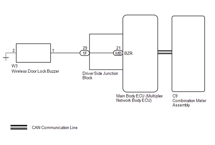
WIRING DIAGRAM
CAUTION / NOTICE / HINT
NOTICE:
The wireless door lock control system uses the CAN communication system. First,
confirm that there is no malfunction in the CAN communication system. Refer to the
How to Proceed with Troubleshooting procedure (See page
.gif) ).
).
PROCEDURE
|
1. |
READ VALUE USING TECHSTREAM (ANSWER-BACK OPERATION) |
(a) Connect the Techstream to the DLC3.
(b) Turn the ignition switch to ON.
(c) Turn the Techstream on.
(d) Enter the following menus: Customize Setting / Wireless Door Lock.
(e) Select the setting by referring to the table below.
|
Display |
Default |
Content |
Setting |
Relevant ECU |
|---|---|---|---|---|
|
Hazard Answer Back |
ON |
When the doors are locked by wireless operation, the hazard warning lights flash once. When the doors are unlocked by wireless operation, the hazard warning lights flash twice. |
OFF or ON |
Main body ECU (Multiplex network body ECU) |
|
Wireless Buzzer Resp |
ON |
Wireless door lock buzzer response |
OFF or ON |
Main body ECU (Multiplex network body ECU) |
|
Wireless Buzzer Vol |
Level 5 |
Wireless door lock buzzer volume |
Level 7, Level 6, Level 5, Level 4, Level 3, Level 2, Level 1 or Level 0 |
Main body ECU (Multiplex network body ECU) |
|
Result |
Proceed to |
|---|---|
|
Both items are ON and except Level 0 |
A |
|
Either item is OFF or Level 0 |
B |
| B | .gif) |
PERFORM CUSTOMIZE FUNCTION |
|
.gif)
|
2. |
CHECK WIRELESS DOOR LOCK CONTROL FUNCTIONS |
(a) Check the wireless door lock control function using the door control transmitter module set sub-assembly.
Result|
Result |
Proceed to |
|---|---|
|
Wireless door lock/unlock operates normally. |
A |
|
Wireless door lock/unlock does not operate normally. |
B |
| B | |
GO TO PROBLEM SYMPTOMS TABLE |
|
|
3. |
READ VALUE USING TECHSTREAM (DOOR UNLOCK DETECTION SWITCH) |
(a) Connect the Techstream to the DLC3.
(b) Turn the ignition switch to ON.
(c) Turn the Techstream on.
(d) Enter the following menus: Body Electrical / Main Body / Data List.
(e) Read the Data List according to the display on the Techstream.
Main Body|
Tester Display |
Measurement Item/Range |
Normal Condition |
Diagnostic Note |
|---|---|---|---|
|
FR Door Lock Pos |
Front door RH unlock detection switch signal/LOCK or UNLOCK |
LOCK: Front door RH locked UNLOCK: Front door RH unlocked |
- |
|
FL Door Lock Pos |
Front door LH unlock detection switch signal/LOCK or UNLOCK |
LOCK: Front door LH locked UNLOCK: Front door LH unlocked |
- |
|
RR-Door Lock Pos SW*1, *3 |
Rear door RH and LH unlock detection switch signal/ON or OFF |
ON: Rear door RH or LH unlocked OFF: Rear door RH and LH locked |
- |
|
RL-Door Lock Pos SW*2, *3 |
Rear door RH and LH unlock detection switch signal/ON or OFF |
ON: Rear door RH or LH unlocked OFF: Rear door RH and LH locked |
- |
- *1: When checking RR- Door Lock Pos SW, make sure to check it with the rear door LH locked.
- *2: When checking RL- Door Lock Pos SW, make sure to check it with the rear door RH locked.
- *3: for Double Cab
OK:
The Techstream should display as shown in the table according to door lock operation.
| NG | |
GO TO LIGHTING SYSTEM (Proceed to Door Unlock Detection Switch Circuit) |
|
|
4. |
CHECK WIRELESS ANSWER-BACK OPERATION |
(a) Check the wireless answer-back operation using the door control transmitter module set sub-assembly.
Result|
Result |
Proceed to |
|---|---|
|
Only wireless door lock buzzer answer-back does not occur. |
A |
|
Only hazard warning light answer-back does not occur. |
B |
| B | |
GO TO STEP 10 |
|
|
5. |
PERFORM ACTIVE TEST USING TECHSTREAM (WIRELESS DOOR LOCK BUZZER) |
(a) Connect the Techstream to the DLC3.
(b) Turn the ignition switch to ON.
(c) Turn the Techstream on.
(d) Enter the following menus: Body Electrical / Main Body / Active Test.
(e) Perform the Active Test according to the display on the Techstream.
Main Body|
Tester Display |
Test Part |
Control Range |
Diagnostic Note |
|---|---|---|---|
|
Wireless Buzzer |
Turns the wireless door lock buzzer |
ON/OFF |
- |
|
Result |
Proceed to |
|---|---|
|
Wireless door lock buzzer does not turn on/off. |
A |
|
Wireless door lock buzzer turns on/off. |
B |
| B | |
REPLACE MAIN BODY ECU (MULTIPLEX NETWORK BODY ECU) |
|
|
6. |
CHECK HARNESS AND CONNECTOR (WIRELESS DOOR LOCK BUZZER - DRIVER SIDE JUNCTION BLOCK) |
(a) Disconnect the W3 wireless door lock buzzer connectors.
(b) Disconnect the 1F driver side junction block connectors.
(c) Measure the resistance according to the value(s) in the table below.
Standard Resistance:
|
Tester Connection |
Condition |
Specified Condition |
|---|---|---|
|
W3-1 - 1F-29 |
Always |
Below 1 Ω |
|
W3-2 - Body ground |
Always |
Below 1 Ω |
|
W3-1 - Body ground |
Always |
10 kΩ or higher |
| NG | |
REPAIR OR REPLACE HARNESS OR CONNECTOR |
|
|
7. |
CHECK DRIVER SIDE JUNCTION BLOCK |
(a) Remove the driver side junction block (See page
).
 Text in Illustration
|
*a |
Component without harness connected (Driver Side Junction Block) |
- |
- |
(b) Measure the resistance according to the value(s) in the table below.
Standard Resistance:
|
Tester Connection |
Condition |
Specified Condition |
|---|---|---|
|
1F-29 - MB-21 (BZR) |
Always |
Below 1 Ω |
| NG | |
REPLACE DRIVER SIDE JUNCTION BLOCK |
|
|
8. |
REPLACE WIRELESS DOOR LOCK BUZZER |
(a) Temporarily replace the wireless door lock buzzer with a new one (See page
).
|
|
9. |
CHECK WIRELESS DOOR LOCK BUZZER OPERATION |
(a) Check the operation of the wireless answer-back function.
OK:
Wireless answer-back function operates normally.
| OK | |
END (WIRELESS DOOR LOCK BUZZER WAS DEFECTIVE) |
| NG | |
REPLACE MAIN BODY ECU (MULTIPLEX NETWORK BODY ECU) |
|
10. |
CHECK HAZARD WARNING LIGHTS OPERATION |
(a) Check that the hazard warning light blinks when the hazard warning signal switch is pressed.
OK:
Hazard warning light signal is normally.
| OK | |
REPLACE MAIN BODY ECU (MULTIPLEX NETWORK BODY ECU) |
| NG | |
GO TO LIGHTING SYSTEM (Proceed to Hazard Warning Switch Circuit) |
 Data List / Active Test
DATA LIST / ACTIVE TEST
1. DATA LIST
HINT:
Using the Techstream to read the Data List allows the values or states of switches,
sensors, actuators and other items to be read without removing any p ...

Other materials:
Reassembly
REASSEMBLY
PROCEDURE
1. INSTALL INDICATOR LIGHT WIRE SUB-ASSEMBLY
(a) Connect the connector to install the indicator light wire sub-assembly
to the shift position indicator.
(b) Attach the clamp to install the indicator light wire sub ...
Pressure Control Solenoid "G" Circuit Open (P280713)
DESCRIPTION
Changing from 1st to 6th is performed by the ECM turning shift solenoid valves
SL1, SL2, SL3 and SL4 on and off. If an open or short circuit occurs in any of the
shift solenoid valves, the ECM controls the remaining normal shift solenoid valves
to allow the vehicle to be operated ...
Black Screen
PROCEDURE
1.
CHECK DISPLAY SETTING
(a) Check that the display is not in "Screen Off" mode.
OK:
The display setting is not in "Screen Off" mode.
NG
CHANGE SCREEN TO SCREEN ON MODE
OK
...
